Multiple sensor for preventing a crown-block incursion on an oil well rig

Active Publication Date: 2005-05-26
KEY ENERGY SERVICES
View PDF8 Cites 40 Cited by
  • Summary
  • Abstract
  • Description
  • Claims
  • Application Information

AI Technical Summary

Benefits of technology

[0006] The present invention improves on the '217 patent technology by providing a system that is both safer and more useful on workover rigs. The technology disclosed herein provides a system that calculates traveling block position, speed, weight, and momentum before applying a braking system to slow down and eventually stop the traveling block. The system takes these parameters into consideration when slowing and/or stopping the traveling block when it reaches a crown out or floor out position. Another embodiment of the present invention involves a multiple sensor system to prevent crown incursions during rig ope

Problems solved by technology

Crown out/floor out can result in equipment damage and/or present a hazard to personnel working on the equipment.
Because it is often not possible for the operator of the cable hoist system to see the position of the traveling block, or because the operator can be otherwise distracted from the position of the traveling block, the operator can inadvertently exceed safe positions of the traveling block.
Although the '217 patent set out to solve the problem of unsafe hoist operation in an oil drilling rig, many

Method used


Image

  • Multiple sensor for preventing a crown-block incursion on an oil well rig
  • Multiple sensor for preventing a crown-block incursion on an oil well rig
  • Multiple sensor for preventing a crown-block incursion on an oil well rig

Examples


Embodiment Construction

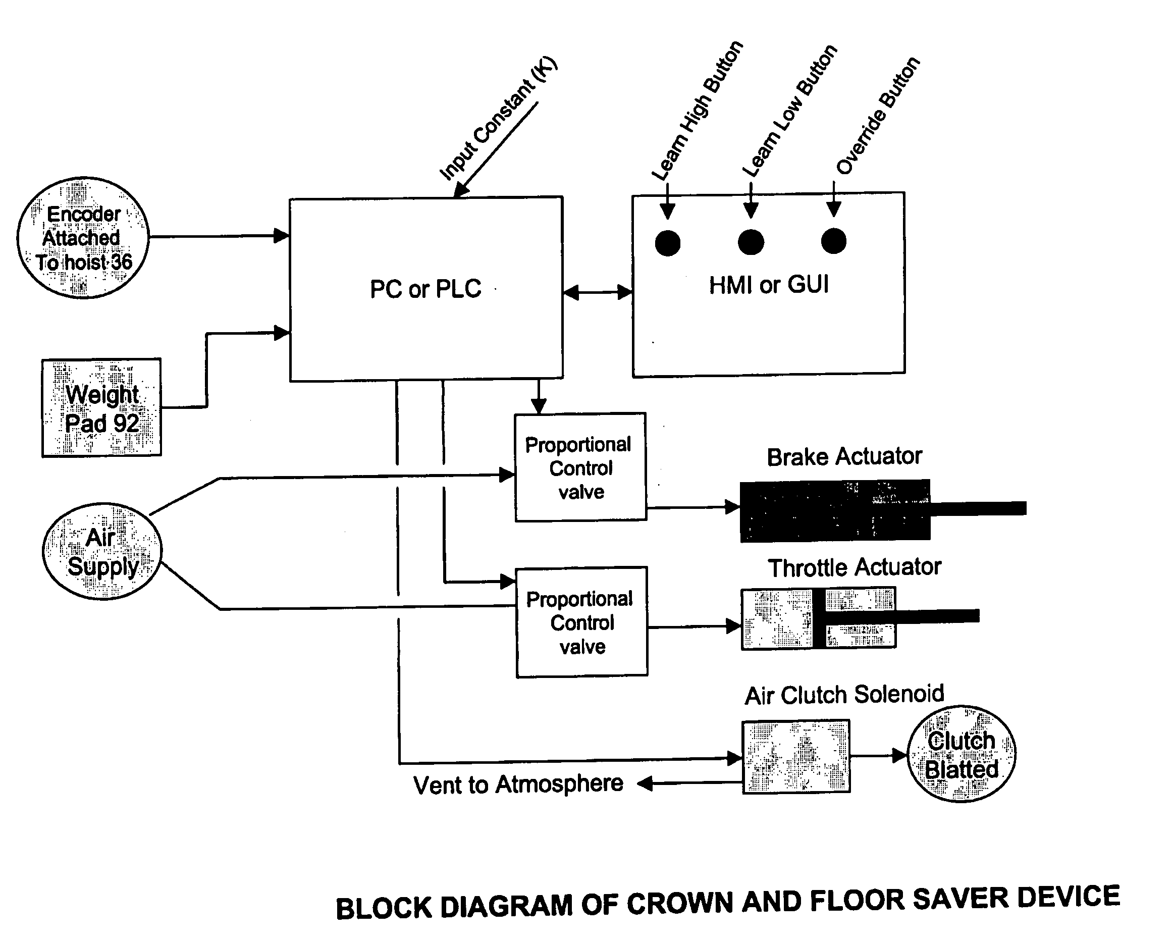
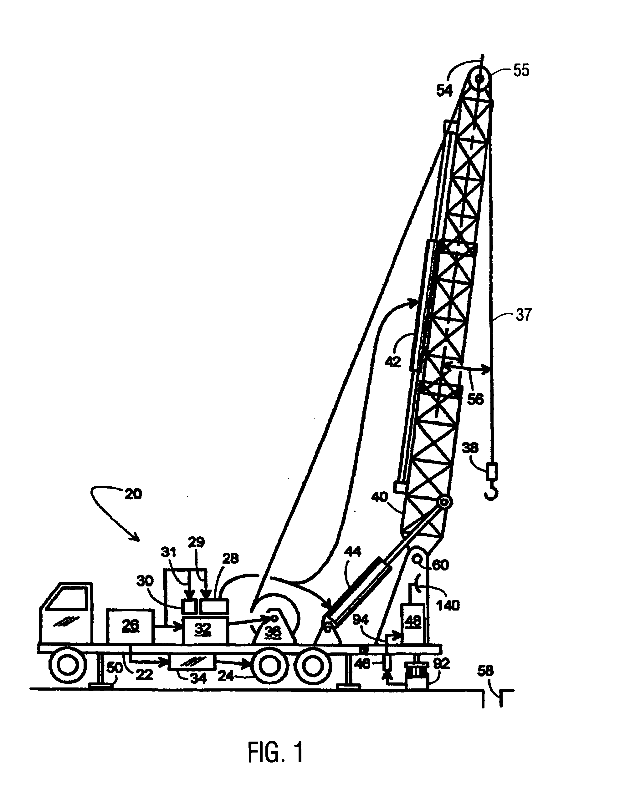
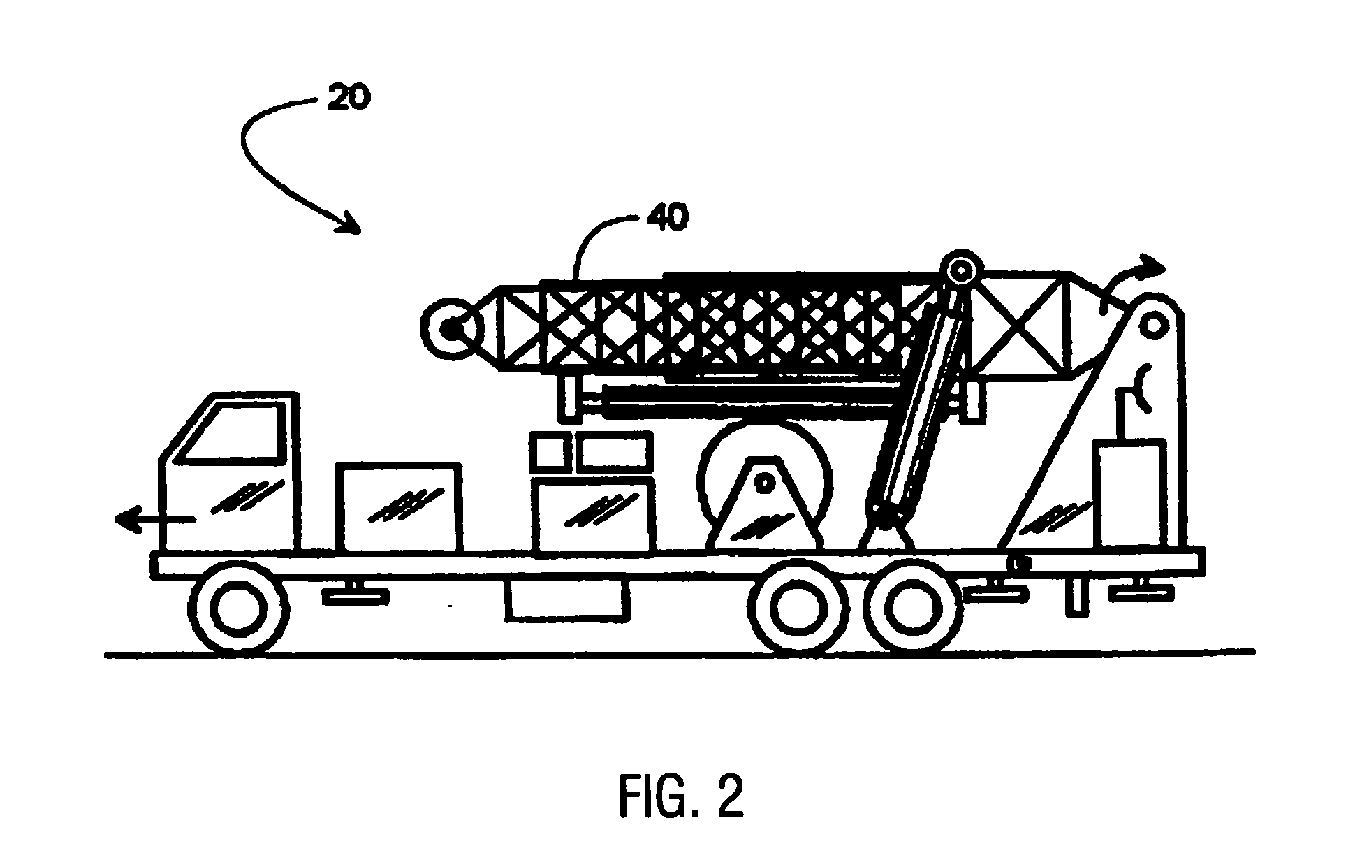
[0021] Referring to FIG. 1, a retractable, self-contained workover rig 20 is shown to include a truck frame 22 supported on wheels 24, an engine 26, a hydraulic pump 28, an air compressor 30, a first transmission 32, a second transmission 34, a variable speed hoist 36, a block 38, an extendible derrick 40, a first hydraulic cylinder 42, a second hydraulic cylinder 44, a monitor 48, and retractable feet 50. Engine 26 selectively couples to wheels 24 and hoist 36 by way of transmissions 34 and 32, respectively. Engine 26 also drives hydraulic pump 28 via line 29 and air compressor 30 via line 31. Compressor 30 powers a pneumatic slip (not shown), and pump 28 powers a set of hydraulic tongs (not shown). Pump 28 also powers cylinders 42 and 44 that respectively extend and pivot derrick 40 to selectively place derrick 40 in a working position (FIG. 1) and in a retracted position (FIG. 2). In the working position, derrick 40 is pointed upward, but its longitudinal centerline 54 is angular...


PUM


Abstract

The technology disclosed herein provides a multiple sensor system that prevents crown incursion by a traveling block in an oil rig. This system calculates traveling block position, traveling block velocity and weight supported by the traveling block, and uses this information to calculate emergency stopping positions to prevent crown out by the traveling block. The system takes all these parameters into consideration when slowing and/or stopping the traveling block when it reaches a crown out position. The result is much safer operation of the traveling block on a workover rig, as well as on an oil drilling rig.

Description

[0001] This application is a continuation in part of co-pending non-provisional application Ser. No. 10 / 720,594, filed Nov. 24, 2003, which in turn was based on provisional application No. 60 / 428,506, filed Nov. 25, 2002.BACKGROUND OF THE INVENTION [0002] After an oil drilling rig drills a well and installs the well casing, the rig is dismantled and removed from the site. From that point on, a mobile repair unit, or workover rig, is typically used to service the well. Servicing includes, for example, installing and removing inner tubing strings, sucker rods, and pumps. This is generally done with a cable hoist system that includes a traveling block that raises and lowers the aforementioned tubing strings, sucker rods, and pumps. [0003] U.S. Pat. No. 4,334,217 describes a system for monitoring the movement of a travelling block on a drilling rig. As described in the '217 patent, the traveling block can be raised or lowered beyond a safe limit. This is called “crown out” if the travel...

Claims


Application Information

Patent Timeline
IPC IPC(8): B66C13/50B66D1/48E21B19/02
CPCB66C13/50E21B19/02B66D1/485
Inventor NEWMAN, FREDERIC M.
Owner KEY ENERGY SERVICES
Why Eureka
Try Eureka