Device for damping movements of structural elements and a bracing system

a technology of structural elements and dampers, applied in the direction of shock proofing, building components, building construction, etc., can solve the problems of not being able to disclose the rotational hinge patent, the cost of typical dampers, and the inability to manufacture and assemble them into the structural frame of a building, so as to achieve constant friction coefficient and dampen grinding noise

Inactive Publication Date: 2005-06-02
MUALLA IMAD H
View PDF2 Cites 20 Cited by
  • Summary
  • Abstract
  • Description
  • Claims
  • Application Information

AI Technical Summary

Benefits of technology

[0009] means for connecting each of the at least two members to respective ones of the structural elements.
[0010] The structural element in civil engineering could be beams, columns and slabs. The wall being dampened may comprise a combination of structural elements as well as non structural elements, and consequently the damper may dampen the movement of both structural and non structural elements. The non structural elements could be windows, doors, infill walls such as brick walls, panels and partition walls.
[0024] The damper device can be mounted in metal towers.
[0025] According to a preferred embodiment of the invention the damper is adapted for damping the movement of prefabricated panels or walls made of timber or light weight metal frames such as frames made from a light weig

Problems solved by technology

If such displacements are large or if they occur periodically they may have serious impact on the conditions of the structure and may cause severe damages or even result in a collapse.
Typical dampers are costly to produce and even more costly to assemble into a structural frame of a building.
Typically a building have

Method used


Image

  • Device for damping movements of structural elements and a bracing system
  • Device for damping movements of structural elements and a bracing system
  • Device for damping movements of structural elements and a bracing system

Examples


Embodiment Construction

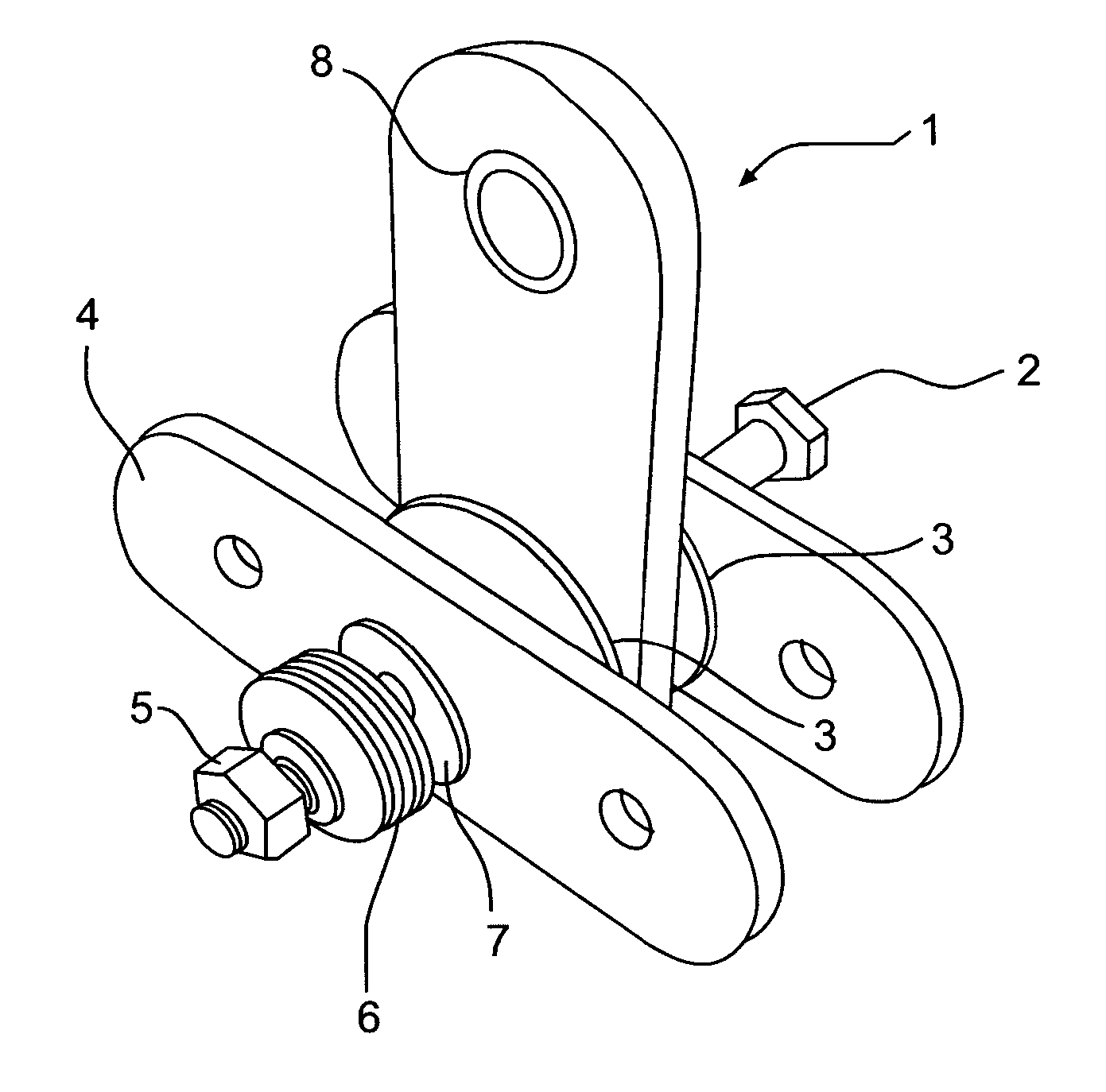
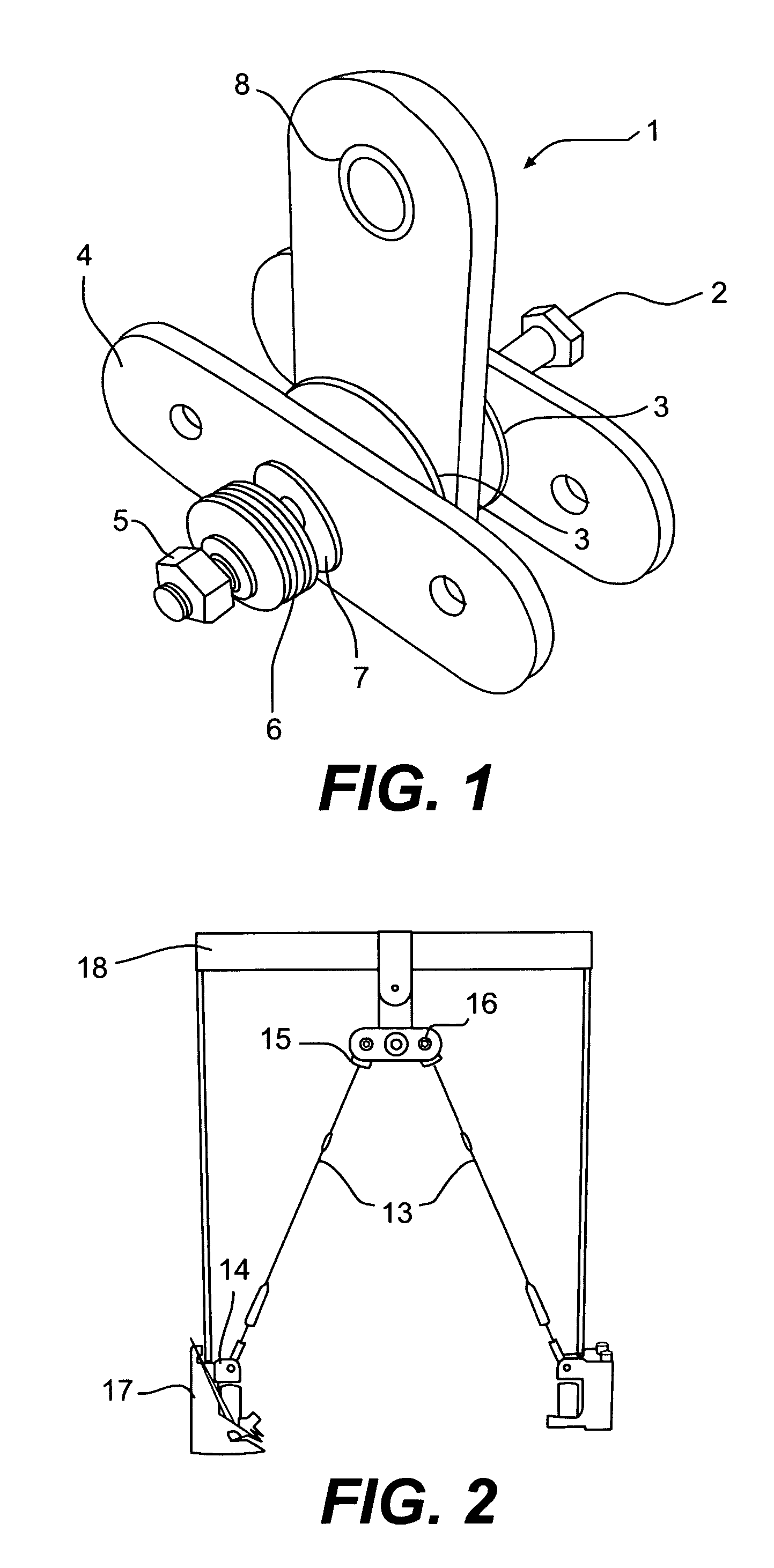
[0005] It is an object of the present invention to provide a damper that is based on a very simple design and comprising parts that are easily produced. At the same time the damper must be easy to assemble and flexible both for arrangement in different bracing systems as well as in confined spaces and both for retrofitting in existing structures as well as for new structures. A further advantage of the present invention is a constant damping effect and a price efficient and reliable system.

[0006] The objects of the invention are fulfilled according to the invention by a device for damping movements of structural and non structural elements in civil engineering structures, the device comprising: [0007] at least two members being interconnected in a rotational joint for frictional damping of relative rotational movement between the at least two members. The device comprises [0008] clamping means for clamping the at least two members together, so as to maintain a clamping force and fr...


PUM


Abstract

The invention relates to the protection of structural systems such as apartment houses against dynamic loading caused by earthquakes, wind, traffic etc. When a frame structure is excited by a horizontal external force, the girders starts to displace horizontally. If such displacements are large or if they occur periodically they may have serious impact on the conditions of the structure and may cause severe damages or even result in a collapse. The present invention relates to a very simply designed and easily produced damper with two members being interconnected in a rotational joint. By means of the arrangement of the damper in the structural system, displacement occurring in the system is transferred to the members being forced to rotate in relation to each other. Frictional resistance between the two members is dampening the rotational movement and thus the displacement in the system. The invention further relates to a device wherein the frictional resistance may be varied dynamically based on the displacements occurring in the system.

Description

TECHNICAL FIELD [0001] This invention generally relates to the protection of structural systems against dynamic loading such as earthquakes or impact from oceanic waves, vibrations from traffic or impact of the wind. More specifically the invention relates to damping of motion or vibration in structures. BACKGROUND OF THE INVENTION [0002] When a frame structure is excited by a horizontal external force, the girders starts to displace horizontally. If such displacements are large or if they occur periodically they may have serious impact on the conditions of the structure and may cause severe damages or even result in a collapse. [0003] Dampers play an important role in the protection of structures such as buildings, and they exist in numerous variants. Dampers are typically damping the motion by means of a frictional force between two moving parts attached to the frame structure of the building or by means of a fluid being pressed to flow between two chambers through a restricted tu...

Claims


Application Information

Patent Timeline
IPC IPC(8): E04H9/02F16F7/04
CPCE04H9/02F16F7/04E04H9/028E04H9/0237
Inventor MUALLA, IMAD H.
Owner MUALLA IMAD H
Why Eureka
Try Eureka