
Device for separation of waste in a vacuum cleaner

a vacuum cleaner and waste technology, applied in the field of vacuum cleaners, can solve the problems of dust accumulation zones, suction sources, and requiring more power, and achieve the effects of reducing the size of the vacuum cleaner, increasing the separation surface area, and simplifying the appliance architectur

Inactive Publication Date: 2005-06-02
SEB SA
View PDF3 Cites 4 Cited by
  • Summary
  • Abstract
  • Description
  • Claims
  • Application Information

AI Technical Summary

Benefits of technology

[0020] The present invention seeks to improve, in particular, the separation of waste within a centrifugal separation device, without increasing the size of the device, and without increasing pressure losses, with the aid of an inexpensive means.

Problems solved by technology

Thus, the performance of such a separator is limited by this phenomenon since the smallest particles are poorly separated.
This results in supplementary pressure drops, thereby requiring more powerful, and thus more costly, suction sources.
It is feared that this can create dust accumulation zones that can become sources for the development of undesired bacteria.

Method used


Image

  • Device for separation of waste in a vacuum cleaner
  • Device for separation of waste in a vacuum cleaner
  • Device for separation of waste in a vacuum cleaner

Examples


second embodiment

[0056]FIGS. 5-10 illustrate the invention.

[0057]FIG. 5 provides an overall view of a vacuum cleaner 70 having a separation device according to the invention. Vacuum cleaner 70 has a case 71 that is supported on several wheels, including a rear wheel 72, the other wheels not being visible in FIG. 5. An aeraulic connection 74 connects case 71 to a nozzle that can be placed in contact with the surface to be cleaned, resulting in the suctioning of waste to the interior of body 71. Body 71 contains a motor-ventilator group (not shown) of conventional construction, for generating a suction air flow capable of suctioning waste present on the surface to be cleaned. A button 76 is provided to turn the vacuum cleaner on and off.

[0058] The separation chamber containing the separation device according to the invention is accessible through a protection cover, or lid, 78. Waste separated by the device is evacuated toward a tank, or other receptacle, 82 that is easily accessible to the user and ...


PUM

PropertyMeasurementUnit
angleaaaaaaaaaa
widthaaaaaaaaaa
lengthaaaaaaaaaa

Abstract

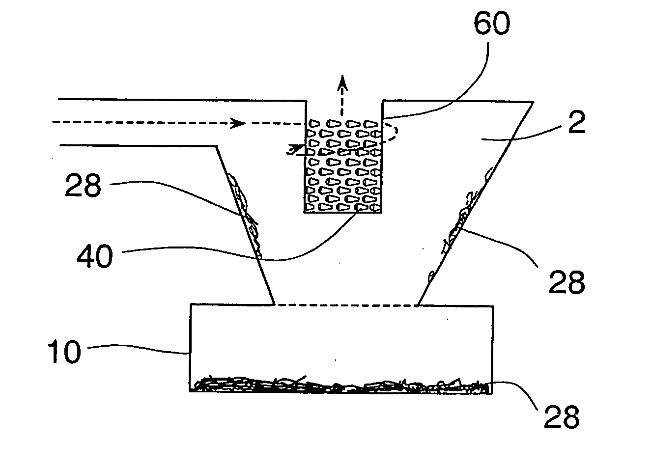
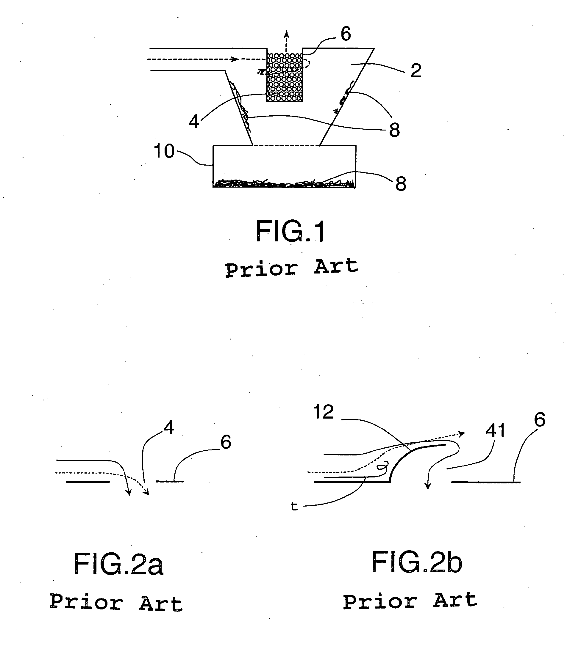
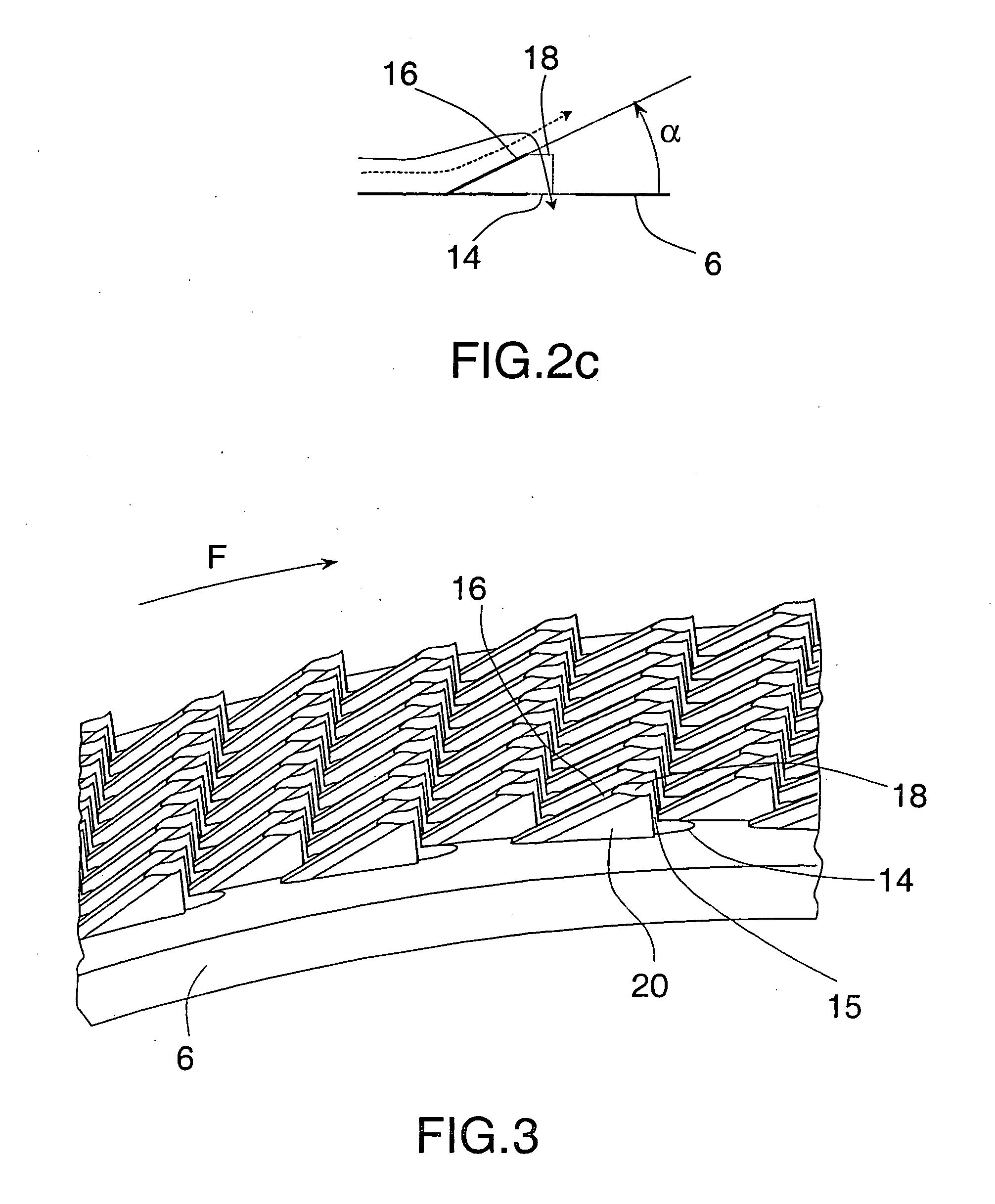
A device for separating and collecting waste entrained by an air flow generated by a suction group in a vacuum cleaner, the device having an air inlet tube opening in a tangential direction into a waste separation chamber, a conduit having a plurality of openings being located in a central part of said chamber, the conduit being in communication with the suction group, and the chamber being connected to a tank for collecting waste. According to the invention, the conduit has inclined walls directed toward the separation chamber, in the direction of circular movement of the air flow in the separation chamber, and the end of each wall has a substantially flat opening that is parallel to the underlying and adjacent conduit. The openings in the conduit are situated in line with the openings in the walls.

Description

BACKGROUND OF THE INVENTION [0001] The present invention concerns appliances of the vacuum cleaner type for picking up dirt, dust, debris, etc., referred to generally herein as “waste”. More particularly, the invention relates to vacuum cleaners that separate the waste from the suction air by centrifuging. [0002] The present invention is directed particularly to improvements in waste separation devices using a generally cylindrical separation chamber, in which air is caused to rotate and exits the chamber through openings provided in a conduit at the center of the chamber. [0003] French patent document 2 786 682, incorporated herein by reference, describes such an appliance having a central conduit is provided at its periphery with a multitude of holes having substantially radially extending axes. A tank for recovering the waste is disposed under the central conduit and closes the separation chamber. [0004] Thus, when the main suction group is in operation, the waste on the floor be...

Claims


Application Information

Patent Timeline
Patent Type & Authority Applications(United States)
IPC IPC(8): A47L9/10A47L9/12A47L9/16B01D45/02
CPCA47L9/1666Y10S55/03B01D45/02A47L9/10A47L9/16
Inventor DAVID, FABIEN
Owner SEB SA
Learn More