
Method and apparatus for drilling a large number of precision holes with a laser

a laser and precision drilling technology, applied in welding apparatus, metal-working equipment, manufacturing tools, etc., can solve the problems of requiring either a precise and expensive mechanical x-y motion system, a large number of precision holes, so as to achieve the desired hole efficiently and optimally, and achieve the effect of avoiding the cost of multiple laser generating systems and sufficient irradian

Inactive Publication Date: 2005-06-02
LASER FARE
View PDF10 Cites 13 Cited by
  • Summary
  • Abstract
  • Description
  • Claims
  • Application Information

AI Technical Summary

Benefits of technology

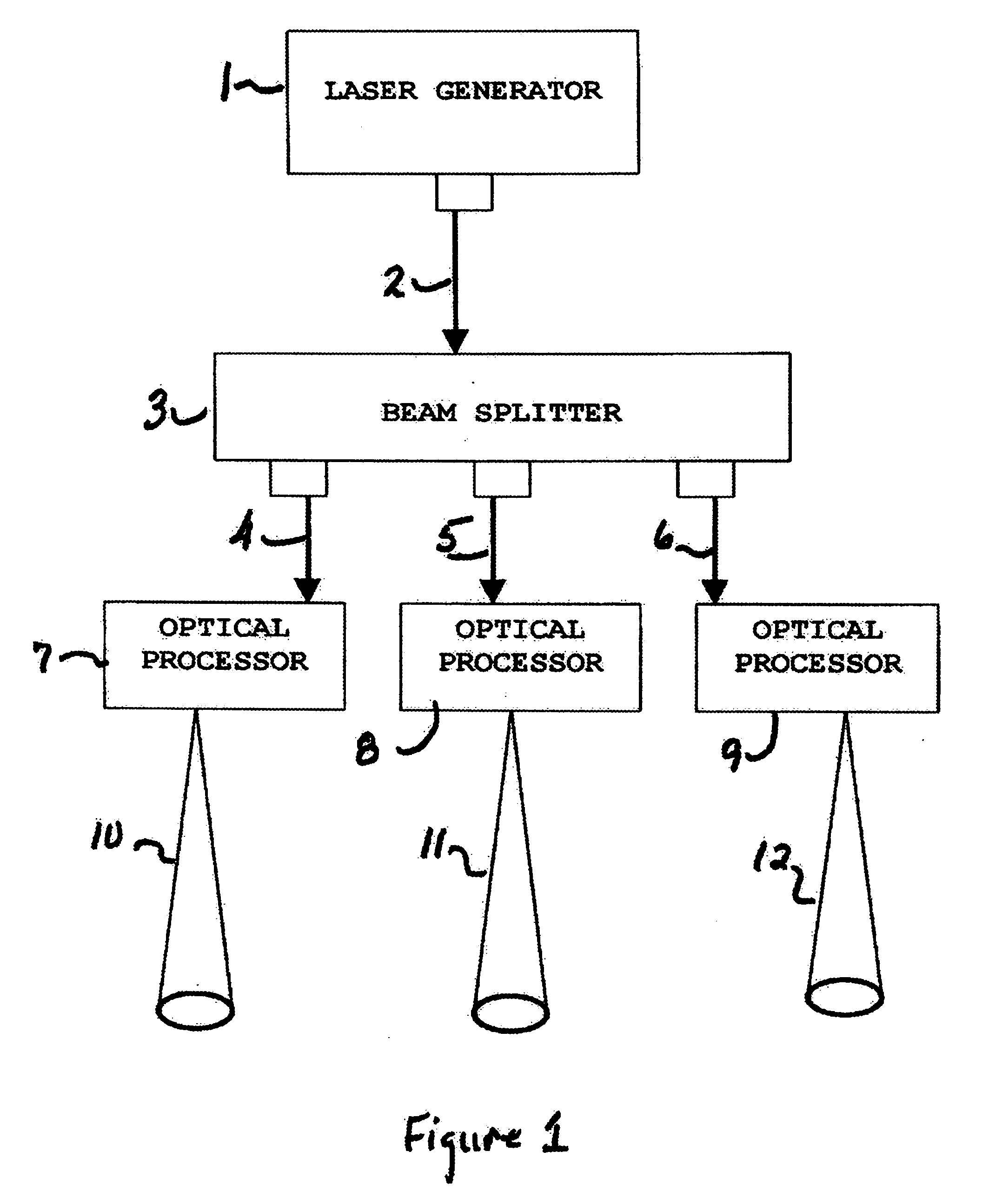
[0011] In the system according to this invention, an optical beam-splitter sub-system is employed to generate multiple laser beams, each possessing sufficient irradiance to efficiently and optimally drill the desired hole. In this manner multiple beams are obtained, while avoiding the cost of multiple laser generating systems, thereby increasing production laser hole drilling speed in a cost effective manner.
[0012] To avoid the need for a system to precisely control the motion of either the work-piece or the laser beam to achieve trepanning with the required precision, a further optical subsystem is constructed to accomplish the equivalent of multiple small holes applied in trepanning.
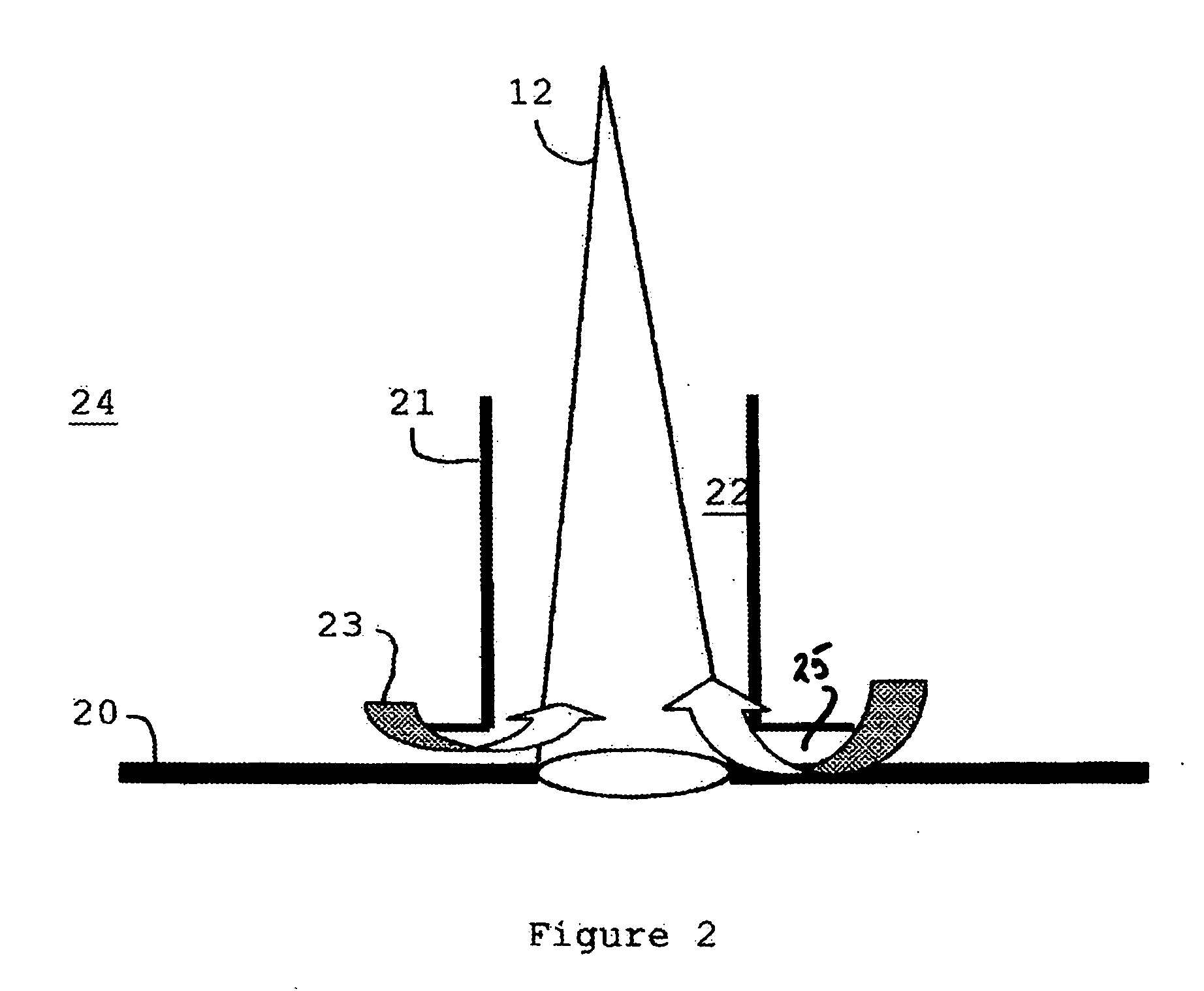
[0014] The resultant annular output beam, when directed onto the target material would operate in a manner substantially similar to conventional mechanical laser trepanning. However, this action would be accomplished without the need for any motion of either the substrate or the laser beam. In this manner the system of this invention would provide superior long-term reliability and precision.
[0015] The use of an optical beam splitter to obtain multiple beams which are each individually optically processed to generate a hole-drilling beam of annular form will enable retention of the precision advantages of trepanning, with the speed advantages associated with drilling multiple holes simultaneously, while avoiding the long-term effects of reduced precision associated with repetitive motion over thousands to millions of cycles.
[0016] In another feature of this invention, Argon gas is also concurrently introduced through a nozzle that is positioned directly in line with the hole. Argon is an inert gas, and hence will not promote any chemical reaction with the material being drilled. Also, with proper adjustment of the nozzle to create the correct flow velocity, this technique can also reduce the amount of recast material condensing on the side-walls of the hole.

Problems solved by technology

However, the disadvantage of laser percussion drilling is that the resulting hole is often less precise than desired.
One disadvantage of trepanning is that in most cases it is significantly slower than percussion drilling.
A second disadvantage is that it requires either a precise and expensive mechanical X-Y motion system to accurately position and move the substrate, or an equally precise and expensive galvanometer driven set of orthogonal mirrors to deflect sequential laser pulses in the desired final hole configuration.
Another disadvantage is the need to program the trepanning motion itself.
Conversely, if the local irradiance is significantly above optimum, the laser drilling time will be brief, but the precision of the drilling process will suffer, especially with respect to the accumulation of excessive recast material and an expanded HAZ.
It has also been found that production lasers sufficiently rugged for “shop floor” applications are very expensive, and can often create local irradiance levels well in excess of the optimum value for a specific material.

Method used


Image

  • Method and apparatus for drilling a large number of precision holes with a laser
  • Method and apparatus for drilling a large number of precision holes with a laser
  • Method and apparatus for drilling a large number of precision holes with a laser

Examples


Embodiment Construction

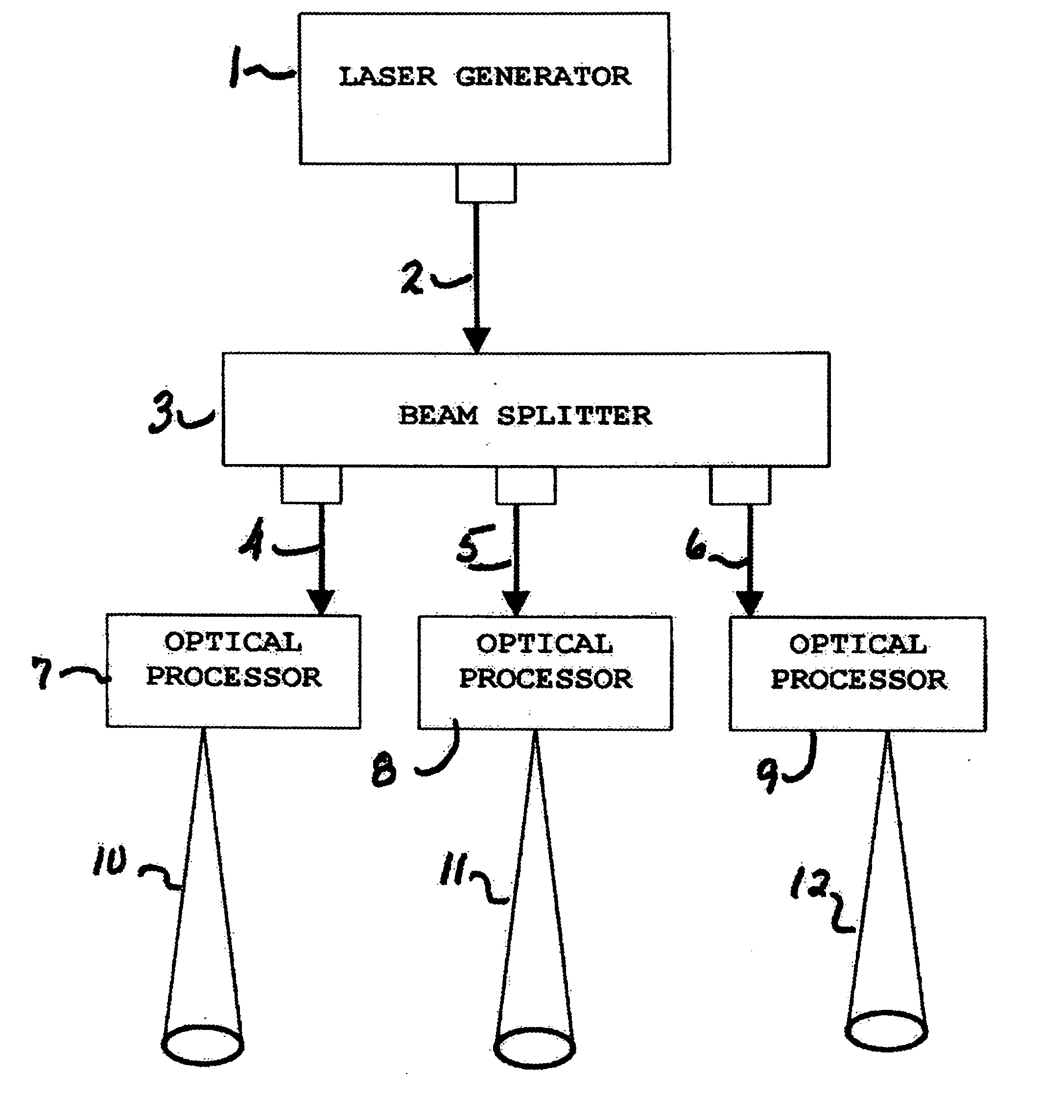
[0022] As shown in FIG. 1, the system of this invention is constructed having laser generator 1 which transmits an output laser beam 2 having an excess irradiance that is well above the optimum level, and thus capable of being divided. Beam splitter 3 receives output laser beam 2 and optically processes beam 2 to divide it into three beams 4-6 of a predetermined optimum irradiance. Beams 4-6 are further optically processed in processors 7-9 to produce annular beams 10-12. Annular beams 10-12 are applied to the target to perform a drilling operation that is substantially similar to laser trepanning.

[0023] In order to obtain the desired number of beams a laser generator is selected, according to one embodiment of this invention, that provides approximately four times the power required to drill a particular material Considering a material, such as Inconel 600, optimum irradiance requires only about ¼th of the full laser power available in existing industrial laser systems. The number...


PUM

PropertyMeasurementUnit
Pressureaaaaaaaaaa
Poweraaaaaaaaaa
Distributionaaaaaaaaaa

Abstract

A laser beam is generated, having a irradiance level sufficient to be divided, is transmitted through a beam splitter that optically processes the beam to divide it into multiple beams having a predetermined irradiance. The multiple beams are further optically transformed to provide an annular irradiance distribution. The annular beams are applied to a target to perform a drilling operation.

Description

RELATED APPLICATION [0001] This application is a conversion of and claims priority from U.S. Provisional Patent Application No. 60 / 525,674, filed Dec. 1, 2003.BACKGROUND OF THE INVENTION [0002] 1. Field of the Invention [0003] This application relates to laser drilling a large number of precision holes. More particularly a method and apparatus is constructed to generate multiple laser beams, each being optically processed to form a narrow annular shaped beam for use in precision drilling small holes. [0004] 2. Brief Description of Related Developments [0005] Laser beams have been used to drill holes for years. Because of the ability to focus a laser beam to a small spot, hole diameters less than 200 micrometers may be obtained without concern for breaking, dulling, or wearing out the very tiny, fragile drill bits. In addition, with sufficient irradiance incident on the target, any material may be drilled regardless of its hardness. Even diamonds have been drilled successfully with a...

Claims


Application Information

Patent Timeline
IPC IPC(8): B23K26/067B23K26/073B23K26/12B23K26/38
CPCB23K26/0639B23K26/0648B23K26/0673B23K26/0734B23K26/386B23K26/127B23K26/1405B23K26/381B23K26/123B23K26/064B23K26/142B23K26/382B23K26/389
Inventor JACOBS, PAUL FRANCIS
Owner LASER FARE
Learn More