
Thermal processing apparatus and thermal processing method

a technology of thermal processing apparatus and thermal processing method, which is applied in the direction of lighting and heating apparatus, muffle furnaces, furnaces, etc., can solve the problems of unrealistic methods and a lot of time and labor, and achieve the effect of suppressing the scattering of substrate pieces

Inactive Publication Date: 2005-06-02
DAINIPPON SCREEN MTG CO LTD
View PDF4 Cites 23 Cited by
  • Summary
  • Abstract
  • Description
  • Claims
  • Application Information

AI Technical Summary

Benefits of technology

[0009] The present invention is intended for a thermal processing apparatus for performing a processing accompanied with heating on a substrate, and it is an object of the present invention to suppress scatter of pieces of a substrate even when the substrate is broken.
[0011] The thermal processing apparatus of the present invention can easily block the periphery of the substrate inside the chamber body when the substrate is heated by the substrate supporting part, and even if the substrate is broken during a processing therefor, it is possible to prevent the pieces of the substrate from being scattered.
[0012] Preferably, thermal conductivity of the substrate supporting part is lower than that of a substrate, and it is thereby possible to uniformly heat the substrate by the substrate supporting part.

Problems solved by technology

In a conventional apparatus, since the pieces of the broken substrate are scattered widely in the thermal processing chamber and penetrate into gaps of a complicated structure, in order to remove the contaminants and recover the function of the apparatus, it is necessary to open (sometimes disassemble) the thermal processing chamber for cleaning of the inside thereof and this needs a lot of time and labor.
Enlarging the susceptor which holds the substrate is a possible method to suppress the scatter of the substrate pieces near the susceptor, but this method is not a realistic one since it leads to upsizing of a whole thermal processing apparatus.

Method used


Image

  • Thermal processing apparatus and thermal processing method
  • Thermal processing apparatus and thermal processing method
  • Thermal processing apparatus and thermal processing method

Examples


Embodiment Construction

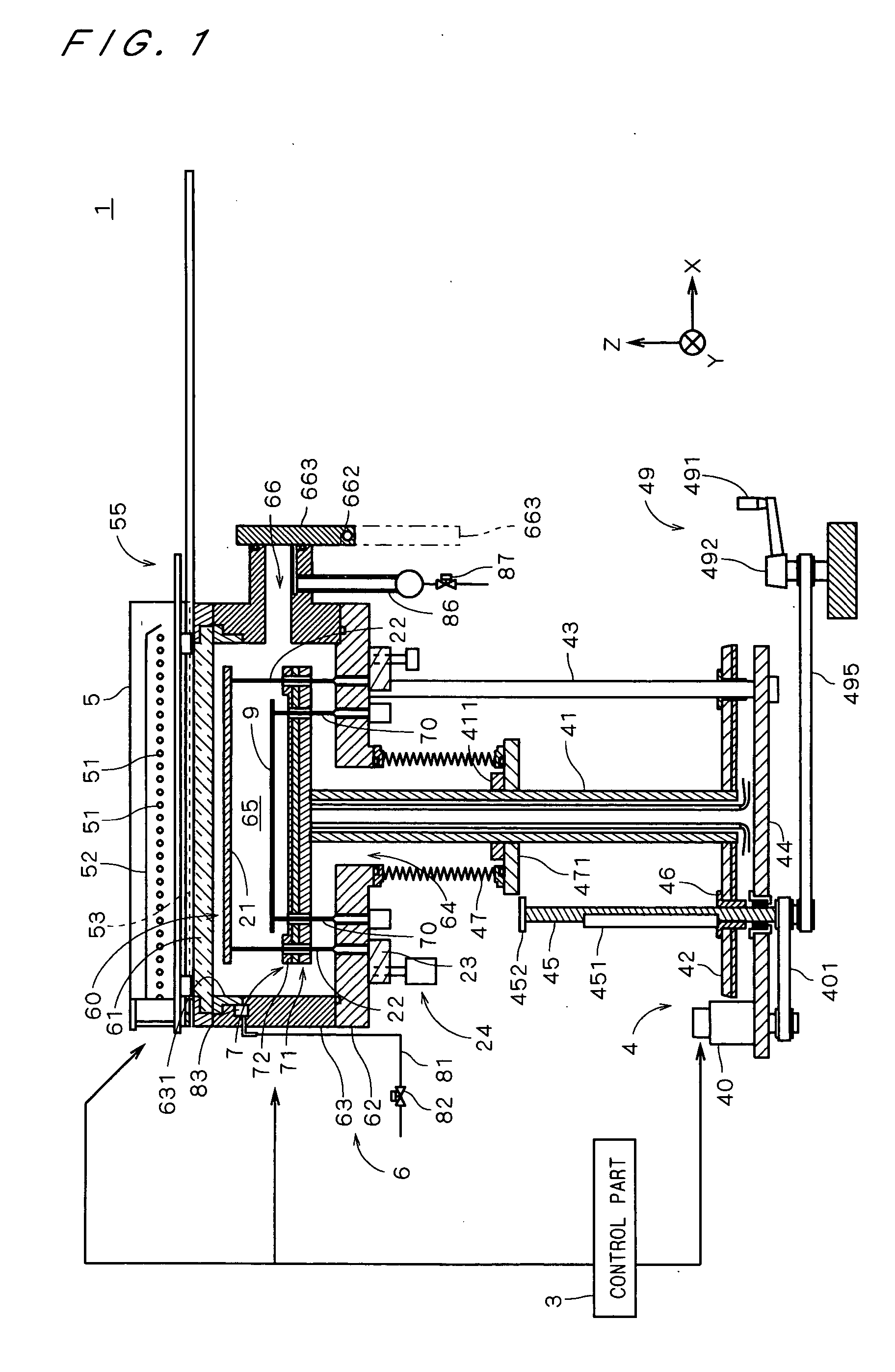
[0031]FIG. 1 is a view showing a construction of a thermal processing apparatus 1 in accordance with one preferred embodiment of the present invention. The thermal processing apparatus 1 is an apparatus for performing a processing accompanied with heating through irradiating a semiconductor substrate 9 (hereinafter, referred to as “substrate 9”) with light.

[0032] The thermal processing apparatus 1 comprises a chamber side part 63 having a substantially-cylindrical inner wall and a chamber bottom 62 covering a lower portion of the chamber side part 63, which constitute a chamber body 6 forming a space (hereinafter, referred to as “chamber”) 65 for thermally processing the substrate 9 and provided with an opening (hereinafter, referred to as “upper opening”) 60 for introducing light in its upper portion.

[0033] The thermal processing apparatus 1 further comprises a transparent plate 61 attached to the upper opening 60 of the chamber body 6, a substantially disk-shaped holding part 7 ...


PUM

PropertyMeasurementUnit
Thicknessaaaaaaaaaa
Thermal conductivityaaaaaaaaaa

Abstract

In a thermal processing apparatus (1), an upper opening (60) of a chamber body (6) is closed by a transparent plate (61) and a light emitting part (5) emits light into the chamber body (6) through the upper opening (60). Inside the chamber body (6) provided are a susceptor (72) for supporting a substrate (9), a hot plate (71) for heating the susceptor (72) and a cover member (21) disposed between the transparent plate (61) and the susceptor (72). The susceptor (72) is provided with a recessed portion whose depth is larger than the thickness of the substrate (9), and a lower surface of the substrate (9) is supported by a bottom surface of the recessed portion and a periphery of the substrate (9) is surrounded by the side wall portion of the recessed portion. During a processing for the substrate (9), the cover member (21) is moved down and brought into contact with an upper end of the side wall portion of the recessed portion to close the recessed portion. This makes it possible to easily block the periphery of the substrate (9) inside the chamber body (6), and as a result, even if the substrate (9) is broken during the processing, it is possible to prevent the pieces of the substrate from being scattered.

Description

BACKGROUND OF THE INVENTION [0001] 1. Field of the Invention [0002] The present invention relates to a thermal processing apparatus for performing a processing accompanied with heating on a substrate and a method therefor. [0003] 2. Description of the Background Art [0004] Conventionally, in various stages of a process for manufacturing a semiconductor substrate or the like (hereinafter, referred to simply as “a substrate”), a thermal processing is performed on the substrate, and a rapid thermal process (hereinafter, referred to as “RTP”) is used as a method of thermal processing. In the RTP, by heating the substrate in a chamber with halogen lamps or the like to raise the temperature thereof up to a predetermined temperature in a short time, it is possible to perform processings which have been hard to execute by a conventional long thermal processing with an electric furnace, such as thinning of an insulating film such as an oxide film, suppressing of rediffusion of impurities (or...

Claims


Application Information

Patent Timeline
IPC IPC(8): F27B17/00F27D5/00H01L21/00H01L21/22H01L21/26H01L21/265H01L21/324H01L21/683
CPCF27B17/0025H01L21/67115H01L21/324F27D5/0037
Inventor HOSOKAWA, AKIHIRO
Owner DAINIPPON SCREEN MTG CO LTD
Learn More