System, apparatus, and method for redistributing forces to meet performance goals and shock wave disturbance constraints

a technology of performance goals and redistributing forces, applied in the field of system, apparatus, and method for redistributing forces to meet performance goals and shock wave disturbance constraints, can solve the problems of difficult environmental issues for a viable supersonic commercial, inability to easily flow around the plane, and negative response and regulatory limitations on supersonic travel. to achieve the effect of minimizing shock wave disturban

Active Publication Date: 2005-06-02
SUPERSONIC AEROSPACE INT
View PDF10 Cites 41 Cited by
  • Summary
  • Abstract
  • Description
  • Claims
  • Application Information

AI Technical Summary

Problems solved by technology

Supersonic flight over the United States and other countries is a challenging environmental issue for a viable supersonic commercial aircraft.
However, for a plane flying at supersonic speeds, the air cannot easily flow around the plane and is instead compressed, generating a pressure pulse through the atmosphere.
Previous research has shown that the highly impulsive nature of the “N-wave” sonic-boom signatures of all existing supersonic aircraft is the primary cause of negative response and regulatory limitations on supersonic travel.
Conclusions of NASA research further indicate the exceptional difficultly of designing an aircraft with an “N-wave” signature of sufficiently low amplitude for general public acceptance.
Aircraft configured according to George-Seebass-Darden's theory for shock minimized distributions are impractical designs because the distributions require: 1. either blunt noses or relaxed bluntness noses whose shapes result in higher drag than minimum drag shapes, which lead to reduced performance; 2. smooth distributions through the engine nacelle region, which is not possible with existing engine designs; 3. a one-dimensional simplifying assumption so the distributions are only calculated directly under the vehicle, which means that non-planar and azimuthally varying effects are not considered; and 4. an expansion behind the aft end of the vehicle to keep the aft shock from coalescing, contrary to a minimum wave drag shape which compresses the flow field for about the last quarter of the vehicle's length.
Achieving a minimized equivalent area distribution is difficult because any change in the area or lift distributions impacts so many other vehicle requirements.
It is extremely computationally intensive to arrive at a design that meets all the constraints and requirements with optimum performance.

Method used


Image

  • System, apparatus, and method for redistributing forces to meet performance goals and shock wave disturbance constraints
  • System, apparatus, and method for redistributing forces to meet performance goals and shock wave disturbance constraints
  • System, apparatus, and method for redistributing forces to meet performance goals and shock wave disturbance constraints

Examples


Embodiment Construction

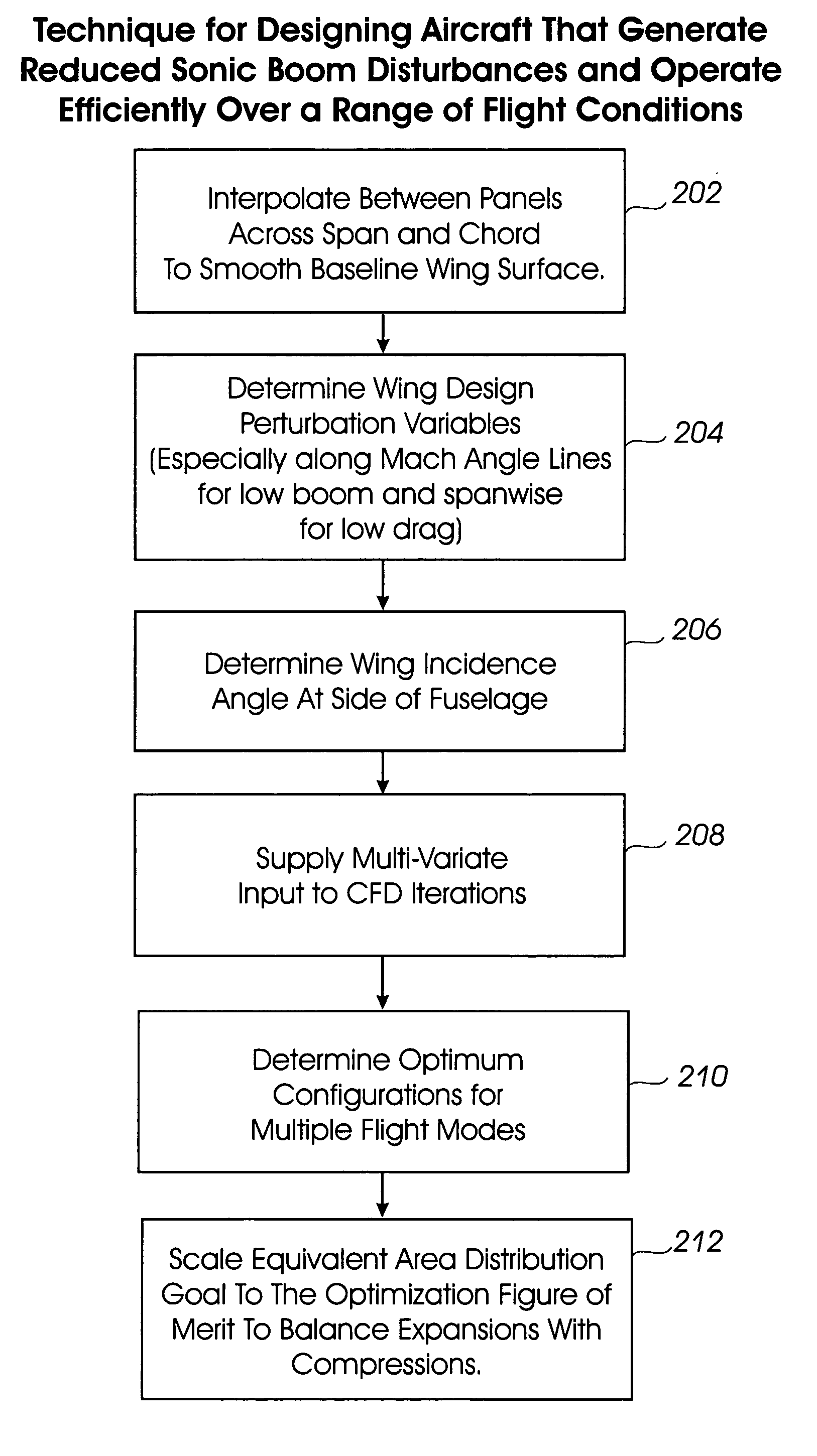
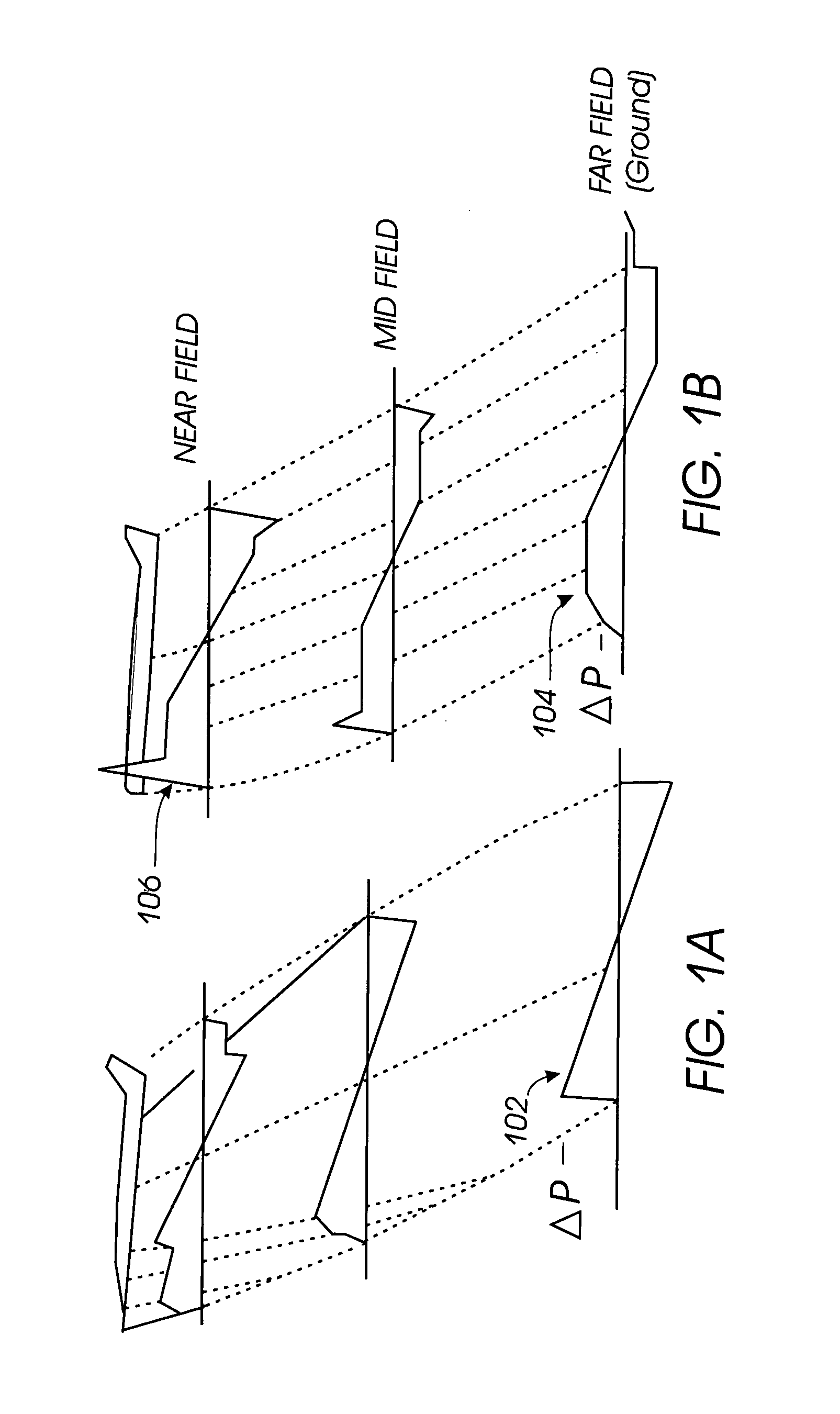
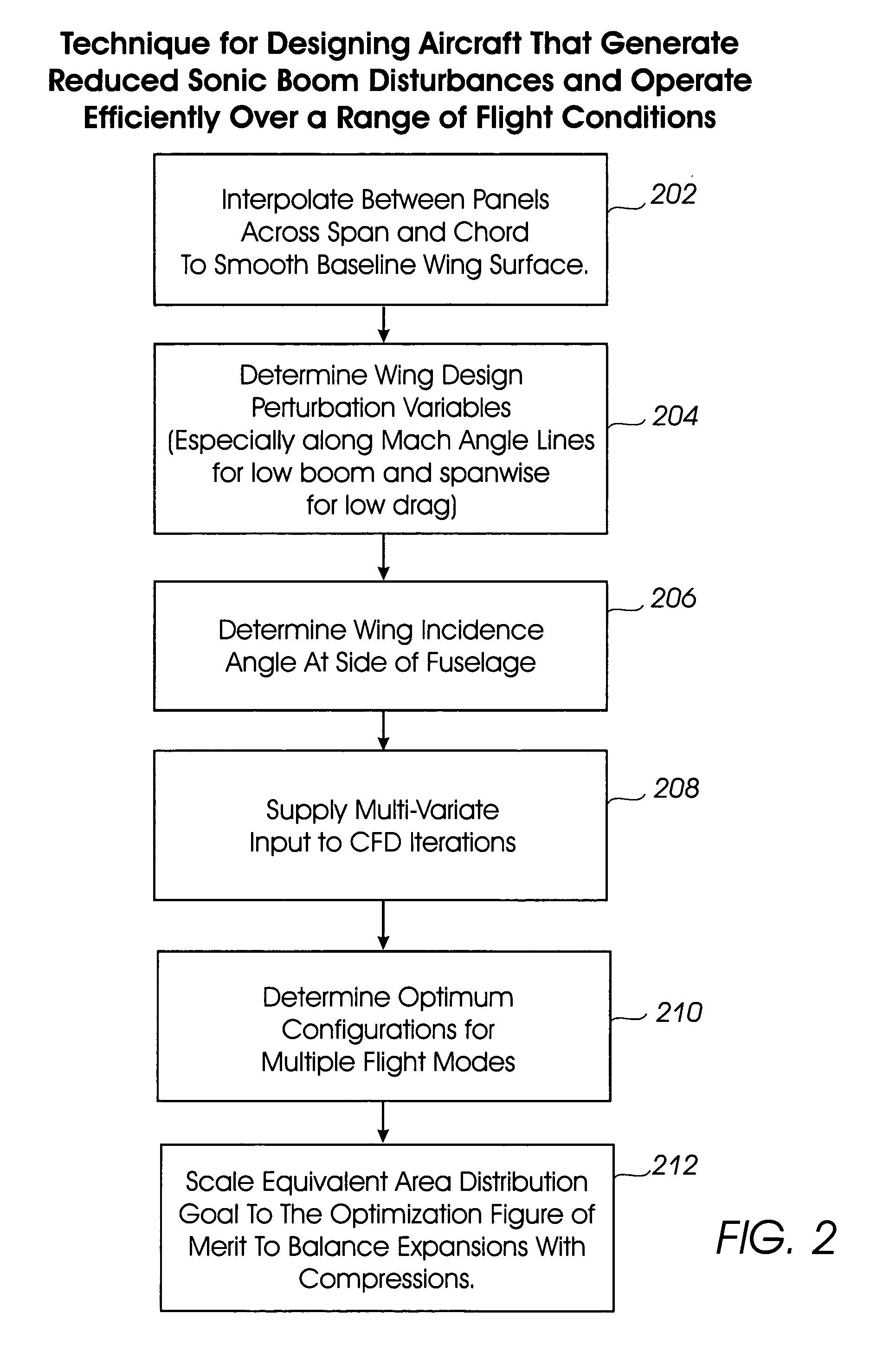
[0035] Shaped sonic boom signatures 104 (FIG. 1B) are achieved by tailoring the volume and lift distribution of an aircraft. In addition to low sonic boom capabilities, a commercially viable supersonic aircraft must have low drag to achieve range, fuel efficiency, and payload goals. FIG. 2 shows an embodiment of a flow diagram of processes 202 through 212 that provide capabilities to design aircraft with low drag (high performance) and reduced sonic boom capabilities.

[0036] Part of the theoretical background for processes 202 through 212 is based on the George-Seebass-Darden theory, which requires the pressure disturbance caused by a low boom aircraft to follow an inversely calculated equivalent area distribution goal 300 to result in the lowest shock strength at the ground. As shown in FIG. 3A, when the equivalent area due to geometric area and lift sum to the equivalent area distribution goal 300, a minimized ground sonic boom is expected. Equivalent area is the Mach angle area d...


PUM


Abstract

A system and method for configuring an aircraft for low sonic boom supersonic flight conditions includes redistributing lift of a wing by configuring the wing with one or more areas of far-field expansion ahead of areas of far-field compression. An equivalent area distribution goal curve is scaled to account for the equivalent area reduction due to excursions below to goal curve. A relaxed constraint allows the equivalent area distribution of the aircraft to be at or below the equivalent area distribution goal curve to enable multiple parameters to be configured to meet the equivalent area distribution constraint, as well as other constraints. The system and method can be adapted to aid in the design of any type of vehicle whose surfaces are subject to supersonic fluid flow, especially to reduce sonic boom.

Description

BACKGROUND OF THE INVENTION [0001] Supersonic flight over the United States and other countries is a challenging environmental issue for a viable supersonic commercial aircraft. Current FAA regulations prohibit civil flights at Mach numbers greater than one without case-by-case exceptions approved by the Administrator. Many other countries have similar restrictions. [0002] A sonic boom occurs due to pressure waves that occur when an aircraft moves at supersonic speeds. During subsonic flight, air displaced by a passing plane flows around the plane in the manner water flows around an object in a stream. However, for a plane flying at supersonic speeds, the air cannot easily flow around the plane and is instead compressed, generating a pressure pulse through the atmosphere. The pressure pulse intensity decreases as a consequence of movement from the airplane, and changes shape into an N-shaped wave within which pressure raises sharply, gradually declines, then rapidly returns to ambie...

Claims


Application Information

Patent Timeline
Patent Type & Authority Applications(United States)
IPC IPC(8): B64C1/00B64C30/00B64D27/18
CPCB64C1/0009B64C30/00Y02T50/44B64D27/18Y02T50/12B64C2001/0045Y02T50/10Y02T50/40
Inventor MORGENSTERN, JOHN M.BACH, JAMES B.ARSLAN, ALAN E.
Owner SUPERSONIC AEROSPACE INT
Why Eureka
Try Eureka