Method of manufacturing a frame assembly

a frame assembly and manufacturing method technology, applied in the direction of vehicle components, superstructure subunits, monocoque constructions, etc., can solve the problems of large number of discrete structural components, unfavorable conditions, and long set-up time, so as to facilitate the manufacture of fast-to-market, cost-effective, and without compromising styling and performan

Inactive Publication Date: 2005-06-02
DANA AUTOMOTIVE SYST GRP LLC
View PDF24 Cites 18 Cited by
  • Summary
  • Abstract
  • Description
  • Claims
  • Application Information

AI Technical Summary

Benefits of technology

[0006] This invention relates to an improved method of manufacturing a vehicular or other frame assembly that facilitates the manufacture of fast-to-market, low-volume, customized frames or other articles in a cost-effective manner, without compromising styling and performance. The method of manufacturing the frame assembly includes the steps of providing an underbody assembly including a plurality of structural components that are secured together so as to be generally planar in shape; providing first and second sidebody assemblies that each include a plurality of structural components that are secured together so as to be generally planar in shape; and securing the underbody assembly to the

Problems solved by technology

This manufacturing method results in a variety of unfavorable conditions.
First, the number of discrete structural components is very large, requiring a large number of stamping tools, assembly fixtures, and welders to assemble them.
Also, a relatively lengthy set-up time is necessary to properly support the plurality of structural components in the desired orientations prior to securement.
Although at least some of these numerous structural components could be combined into relatively large, monolithic stampings to facilitate the assembly process, the manufacture of such physically large stampings would likely require enormous and expensive tools and presses.
Second, a large amount of the welding of the assembly must typically take place in the final manufacturing location (i.e., not at the manufacturing location of a supplier to its customer).
This increases the amount of capital and tooling that is required by the customer to manufacture the frame assemblies and reduces the opportunities for outsourcing from the customer to the supplier.
Third, resistance spot welding and other conventional welding techniques typically have a relatively long cycle time, resulting in low weld speeds.
Also, the weld tips usually require frequent maintenance in the form of cleaning and dressing, which further hampers productivity.
These cleaning issues, while a minor inconvenience with steel alloys, can become more pronounced

Method used


Image

  • Method of manufacturing a frame assembly
  • Method of manufacturing a frame assembly
  • Method of manufacturing a frame assembly

Examples


Embodiment Construction

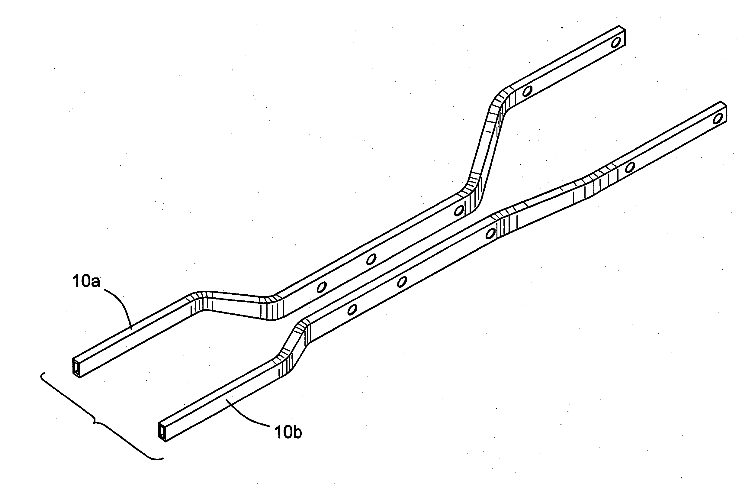
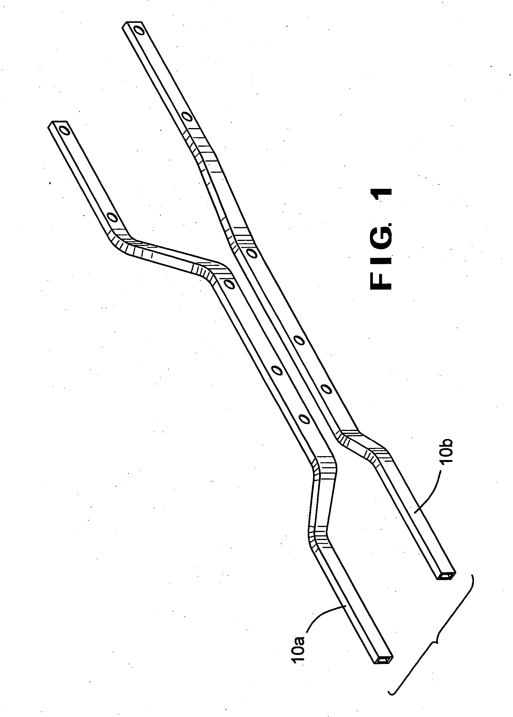
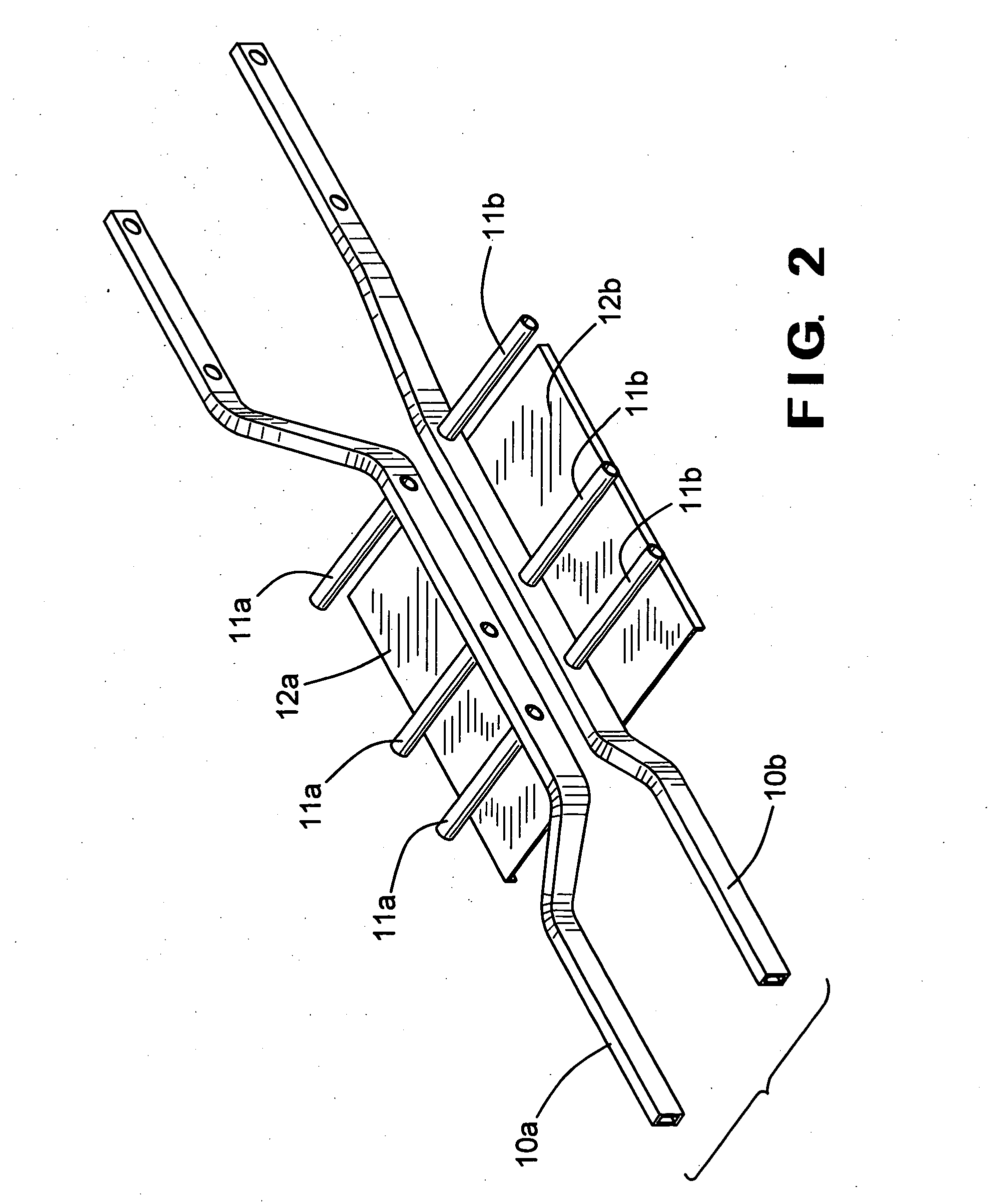
[0025] Referring now to the drawings, there is illustrated in FIGS. 1 through 5 a method of manufacturing an underbody assembly for use in a vehicle or other frame assembly in accordance with this invention. In a first step of the method illustrated in FIG. 1, first and second longitudinally extending beams 10a and 10b are provided. The first and second longitudinal beams 10a and 10b can be formed from any desired material or combination of materials and may have any desired shape or shapes, including different shapes than as shown. Each of the illustrated first and second longitudinal beams 10a and 10b is formed from a single, closed channel structural member. However, either or both of the first and second longitudinal beams 10a and 10b can be formed from an assembly of multiple pieces. Furthermore, either or both of the first and second longitudinal beams 10a and 10b can be formed either partially or completely from open channel structural members. In the illustrated embodiment, ...


PUM


Abstract

A method of manufacturing a frame assembly includes the steps of providing an underbody assembly including a plurality of structural components that are secured together so as to be generally planar in shape; providing first and second sidebody assemblies that each include a plurality of structural components that are secured together so as to be generally planar in shape; and securing the underbody assembly to the first and second sidebody assemblies to form a frame assembly. The underbody assembly can be formed by securing first and second longitudinally extending, closed channel beams to a plurality of closed channel cross members. Each of the sidebody assemblies can be formed by securing a closed channel lower rocker rail and closed channel upper roof rail to a plurality of pillars. Each of the pillars can be formed by initially securing a first stamping to the lower rocker rail and the upper roof rail, then securing a second stamping to each of the first stampings. The underbody assembly can be secured to the first and second sidebody assemblies by magnetic pulse welding to form the frame assembly.

Description

CROSS-REFERENCE TO RELATED APPLICATIONS [0001] This application claims the benefit of U.S. Provisional Application No. 60 / 512,167, filed Oct. 17, 2003, the disclosure of which is incorporated herein by reference.BACKGROUND OF THE INVENTION [0002] This invention relates in general to methods of manufacturing frame assemblies. In particular, this invention relates to an improved method of manufacturing a vehicular frame assembly that facilitates the manufacture of fast-to-market, low-volume, customized vehicles in a cost-effective manner. [0003] Many land vehicles in common use, such as automobiles, vans, and trucks, include a frame assembly that is supported upon a plurality of ground-engaging wheels by a resilient suspension system. The structures of known frame assemblies can be divided into two general categories, namely, separate and unitized. In a typical separate frame assembly, the structural components of the frame portion of the vehicle are separate and independent from the ...

Claims


Application Information

Patent Timeline
IPC IPC(8): B62D21/10B62D23/00B62D25/02B62D25/20B62D65/02B62D65/04
CPCB62D21/10B62D23/00B62D65/04B62D25/2036B62D65/02B62D25/02
Inventor MCGILL, SCOTT M.SIMBOLI, ANDREW R.RAGER, CHRISTOPHER A.
Owner DANA AUTOMOTIVE SYST GRP LLC
Why Eureka
Try Eureka