Light emissive display device

a display device and light emissive technology, applied in the direction of discharge tube luminescnet screens, discharge tube/lamp details, electric discharge lamps, etc., can solve the problems of increasing the current amount, not only affecting the life of the display device, and the subpixels of r, g, and b cannot be determined simply, so as to facilitate circuit layout design and facilitate circuit layout design. , the effect of high aperture ratio

Inactive Publication Date: 2005-06-02
SANYO ELECTRIC CO LTD
View PDF22 Cites 65 Cited by
  • Summary
  • Abstract
  • Description
  • Claims
  • Application Information

AI Technical Summary

Benefits of technology

[0025] According to the present invention, because the horizontally adjoining subpixels are provided with the same height, a selection line extending, for example, in the row direction for operating each subpixel can be linearly disposed without meandering, thereby facilitating circuit layout design.
[0026] Further, because the vertically adjoining subpixels have the same width, lines extending in the column direction, such as a video signal line and a power source line, can be disposed without meandering. The lines can be linearly disposed perpendicular to the above selection line and the like extending in the row direction, thereby facilitating circuit layout design and achieving a high aperture ratio.
[0027] Even when a pixel is formed of four subpixels for four colors of R, G, B, and white (W) provided separately therefrom, the subpixel layout achieving light emission with a high luminance while requiring less amount of current per pixel can easily be designed taking into consideration dependency on the wavelength of emitted light of a light emissive element, dependency on transmission wavelength of a color filter, and the like. Therefore, the area ratio thereof can also be easily changed.
[0028] Accordi

Problems solved by technology

Although an image can be displayed with a high luminance by increasing the amount of supplied current because light emission intensity of the EL element depends on the amount of current supplied to each EL element, increasing the amount of current not only elevates power consumption in the EL element, but also tends to shorten the life of the display device.
Further, in a full color display, the white light itself cannot be directly substituted by

Method used


Image

  • Light emissive display device
  • Light emissive display device
  • Light emissive display device

Examples


Embodiment Construction

[0038] A best mode to practice the present invention (hereinafter referred to as an embodiment) will now be described with reference to the accompanying drawings.

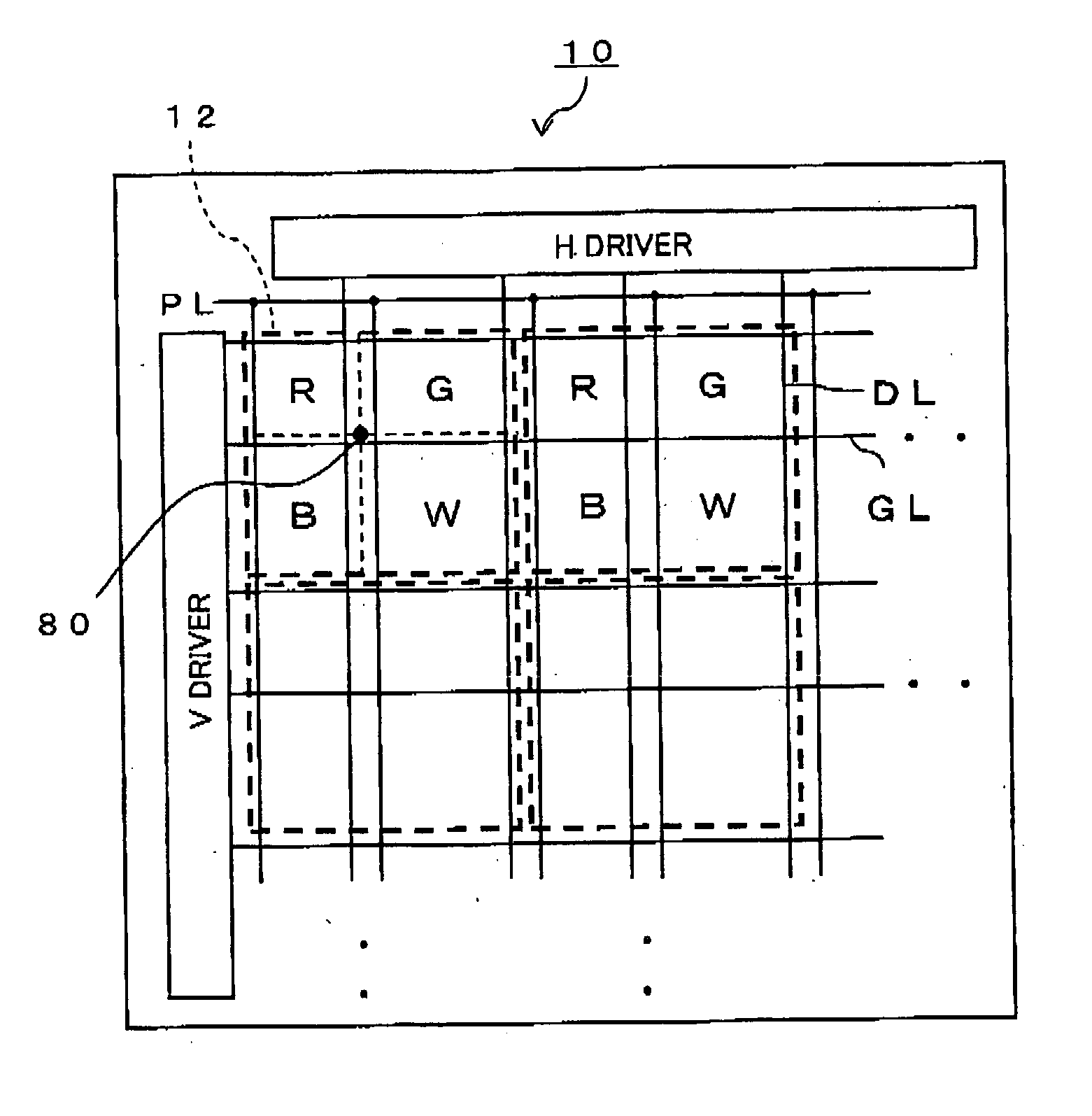
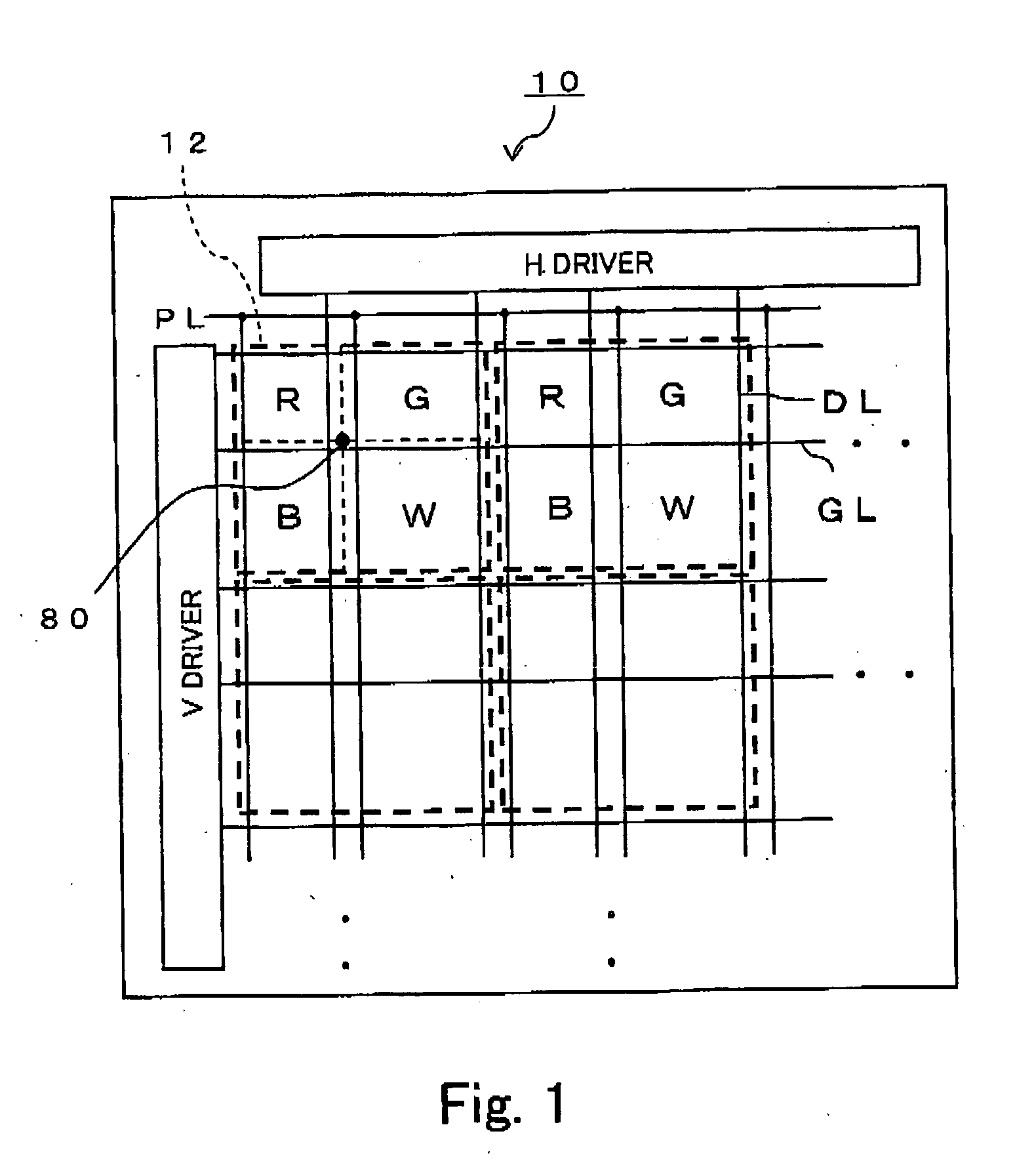
[0039]FIG. 1 shows a concept of arranging pixels 12 in a light emissive display device 10 according to an embodiment of the present invention. The display device 10 includes a plurality of substantially quadrangular (the area surrounded by a thick broken line in FIG. 1) pixels 12 arranged in a matrix at a display portion on a substrate. Each pixel 12 includes four subpixels of R, G, B, and W, emitting different colors of light. By thus combining the W subpixel to the R, G, and B subpixels to form a single pixel, an image with a higher white component, such as an outdoor landscape, can be displayed using less power.

[0040] According to the present embodiment, a checkerboard arrangement of 2 rows by 2 columns is employed for arranging the four subpixels of the pixel 12. While the R, G, B, and W subpixels may be arranged in a...


PUM


Abstract

In a display device using, for example, an organic EL element as a light emissive element, a single pixel is formed of subpixels of four colors, R, G, B, and W, arranged in two rows and two columns. Each pixel is substantially quadrangular in shape, and at least one of the subpixels in the pixel has an area different from the areas of the other subpixels. The subpixels of the colors horizontally adjoining in the same row have the same height, and the subpixels of the colors vertically adjoining in the same column have the same width. Even when the area ratio of the subpixels is varied by changing the position of the intersecting point of divisional lines dividing a pixel into four subpixels, the design can easily be modified by satisfying the above relationship, and a display device with a high luminance and a long life can easily be obtained with any area ratio.

Description

CROSS-REFERENCE TO RELATED APPLICATIONS [0001] The priority Japanese Patent Applications, Numbers 2003-342468, 2004-272635 and 2004-272636, upon which this patent application is based are hereby incorporated by reference. BACKGROUND OF THE INVENTION [0002] 1. Field of the Invention [0003] The present invention relates to light emissive display devices having a light emissive element, such as an electroluminescence (EL) element, and, more particularly, to a light emissive display device in which each pixel includes a plurality of subpixels corresponding to different colors. [0004] 2. Description of the Related Art [0005] Much attention is focused on self-emissive display devices, such as EL display devices using an organic EL element, as next-generation flat display devices (flat panel displays) and potential replacements for liquid crystal display devices. A typical EL light emissive display device includes a plurality of pixels, each including an EL element, arranged, for example, ...

Claims


Application Information

Patent Timeline
IPC IPC(8): H01J1/62H01J63/04H01L27/32
CPCH01L27/3213H01L27/322H01L27/3216H01L27/3218H01L27/326H10K59/351H10K59/352H10K59/353H10K59/38H10K59/121
Inventor MATSUMOTO, SHOICHIROMAMENO, KAZUNOBU
Owner SANYO ELECTRIC CO LTD
Why Eureka
Try Eureka