Multi-band antenna structure

a multi-band antenna and antenna technology, applied in the field of antenna structures, can solve the problems of increasing the cost of the final product, and the cost of the external antenna and its associated conductors, so as to shorten the length of the radiating element. the effect of the radiating elemen

Active Publication Date: 2005-06-02
DSP GROUP
View PDF69 Cites 36 Cited by
  • Summary
  • Abstract
  • Description
  • Claims
  • Application Information

AI Technical Summary

Benefits of technology

[0009] The dimensions of the inductive and capacitive elements may be chosen such that at lower radio frequencies, e.g., 2.4 GHz, the inductive components act as short circuits, in turn lengthening the radiating elements of the antenna structure. At higher radio frequencies, e.g., 5.0 GHz, the inductive components act as open circuits, thereby shortening the lengths of the radiating elements and thereby achieving a radiating element at

Problems solved by technology

A general problem in the design of mobile computers and other types of small, portable, wireless data communication products is the radiating

Method used


Image

  • Multi-band antenna structure
  • Multi-band antenna structure
  • Multi-band antenna structure

Examples


Embodiment Construction

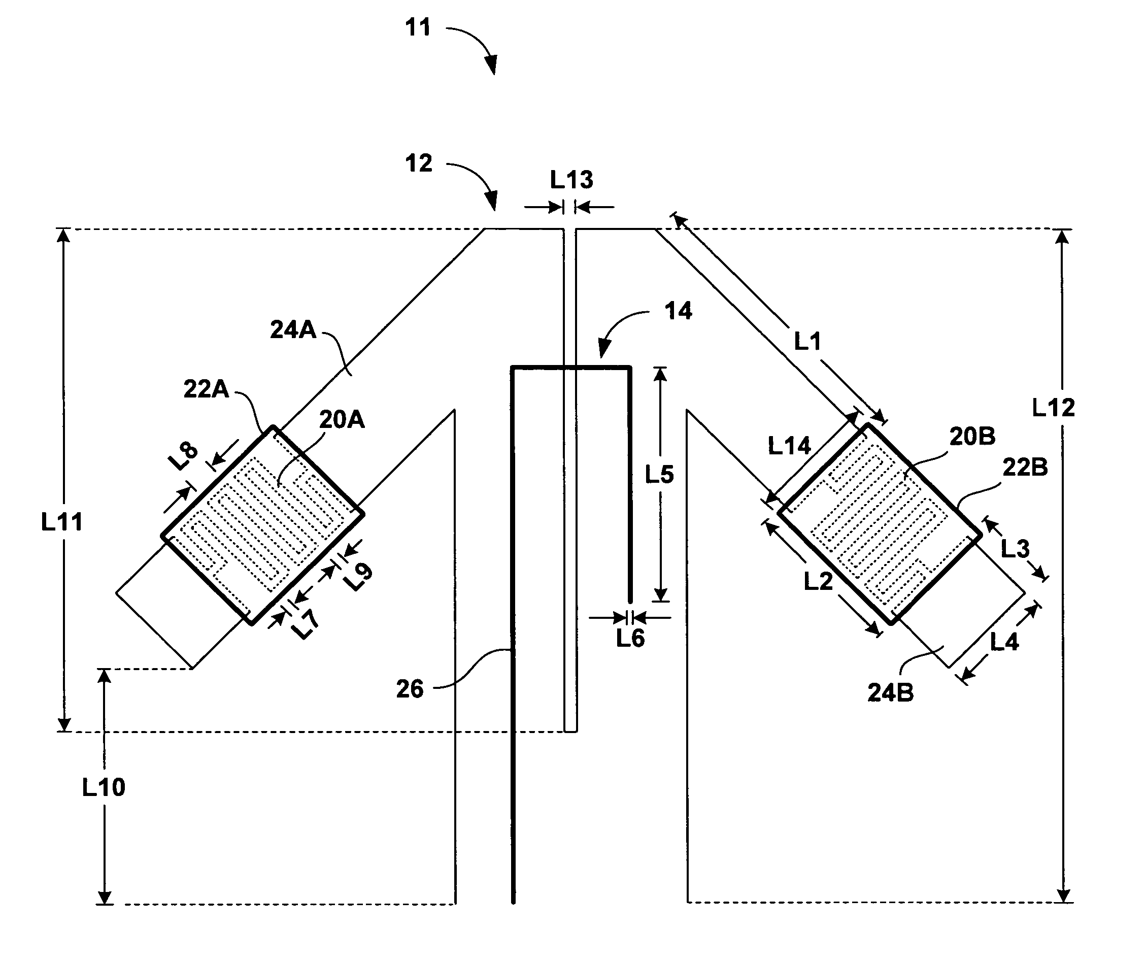
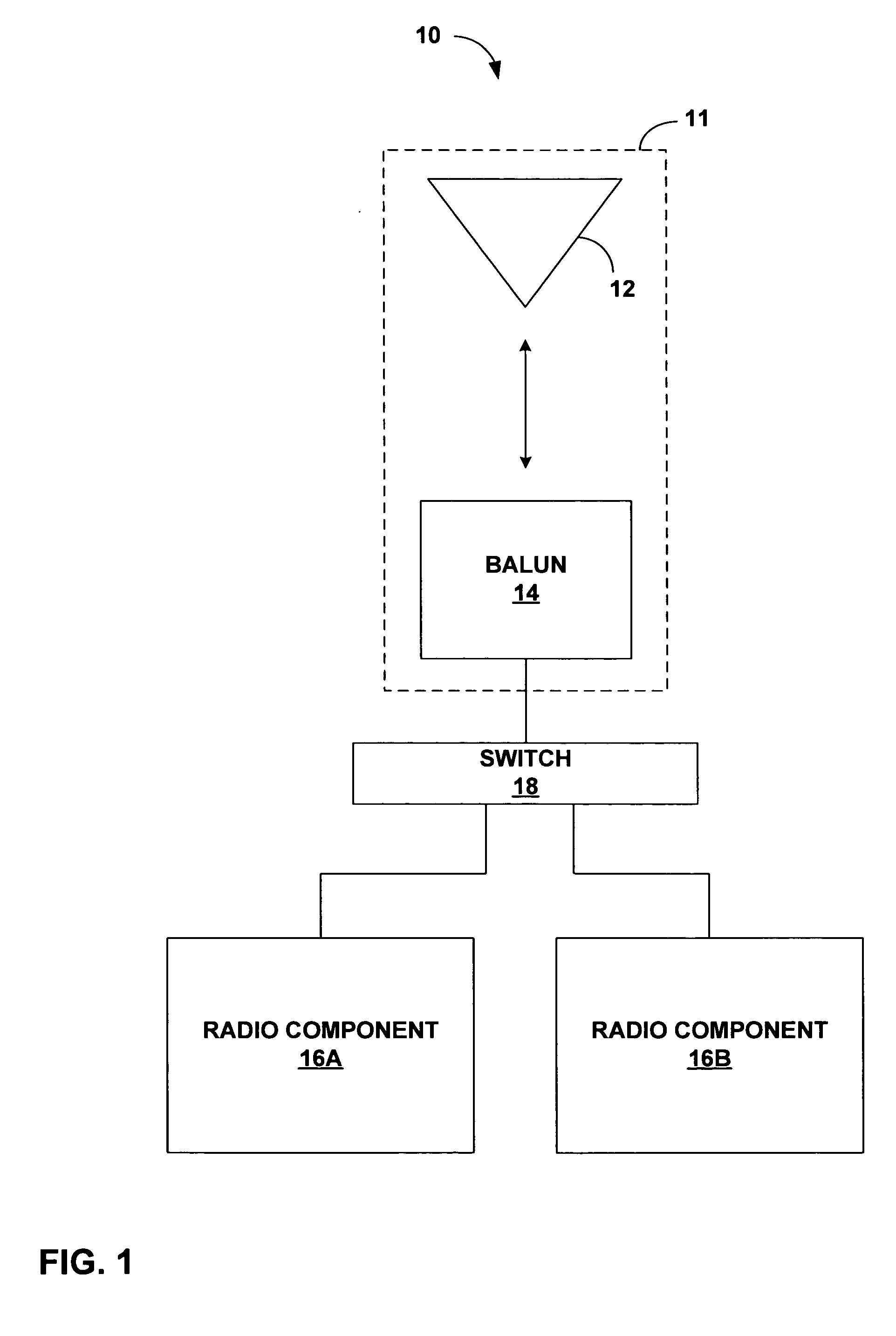
[0021]FIG. 1 is a block diagram illustrating a system 10 for wireless communication. System 10 includes a multi-band antenna structure 11 that includes a radiating component 12 and a conductive strip feed-line (not shown) that electromagnetically couples to radiating component 12. As will be described, multi-band antenna structure 11 is created to radiate and tune energy at more than one frequency, thus making antenna structure 11 a multi-band antenna structure. In this manner, a single antenna structure may operate within multiple frequency bands, thus reducing the amount of planar space needed on a circuit structure for multiple antennas. For exemplary purposes, the techniques of the invention will be described with respect to an antenna structure that operates within two frequency bands, i.e., a dual-band antenna structure. However, the techniques may be applied to antenna structures that operate at more than two frequency bands.

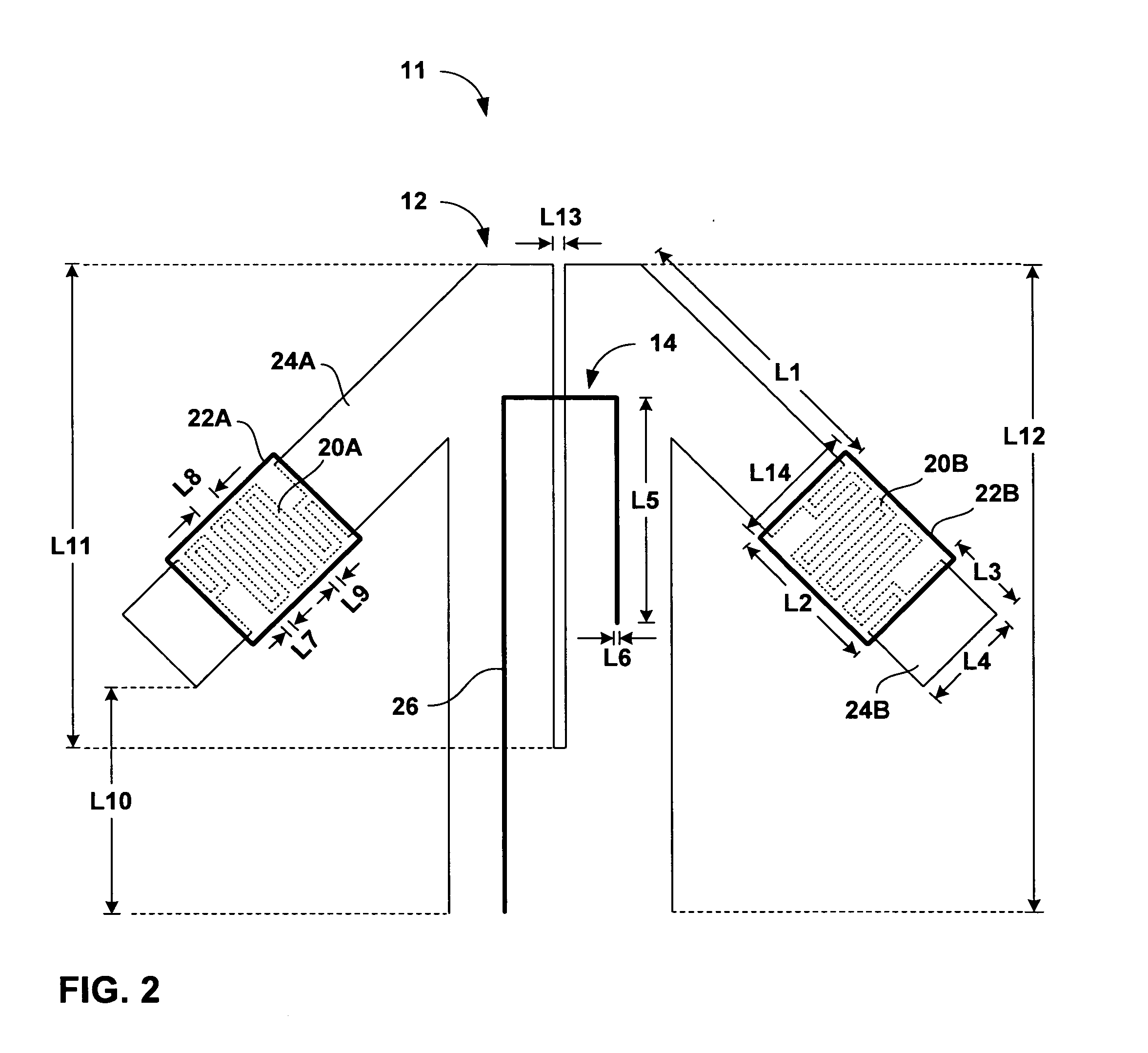
[0022] In particular, antenna structure 11 include...


PUM


Abstract

The invention provides a multi-band antenna structure for use in a wireless communication system. The antenna structure includes integrated inductive elements and capacitive elements that function as a tuned circuit to allow the antenna structure to operate in multiple frequency ranges. In particular, the capacitive elements electromagnetically couple to the inductive elements. The capacitive elements provide the inductive elements with parallel capacitance at a given set of frequencies, thereby providing the antenna structure with frequency selectivity. At a particular frequency range, the inductive elements act as short circuits, thereby lengthening the radiating elements, which radiate energy at the particular frequency. At another frequency range, the inductive components act as open circuits, virtually shortening the radiating elements in order to radiate the higher frequencies. In this manner, the multi-band antenna structure operates within multiple frequency ranges.

Description

[0001] This application claims the benefit of U.S. provisional application No. 60 / 515,020, filed Oct. 28, 2003, the entire content of which is incorporated herein by reference.TECHNICAL FIELD [0002] The invention relates to antenna structures for use in a wireless communication system and, more particularly, to multi-band antenna structures. BACKGROUND [0003] With the advent of mobile computers, there has been an increased demand to link such devices in a wireless local area network (WLAN). A general problem in the design of mobile computers and other types of small, portable, wireless data communication products is the radiating structure required for the unit. An external dipole or monopole antenna structure can be readily broken in normal use. Also, the cost of the external antenna and its associated conductors can add to the cost of the final product. [0004] In an effort to avoid use of an external antenna, manufacturers have begun to produce devices with embedded antennas. An e...

Claims


Application Information

Patent Timeline
IPC IPC(8): H01Q1/22H01Q1/24H01Q1/36H01Q5/00H01Q5/321H01Q9/28H01Q9/36H01Q21/29H01Q23/00
CPCH01Q1/22H01Q1/2258H01Q1/2275H01Q1/243H01Q5/321H01Q9/285H01Q9/36H01Q21/29H01Q23/00H01Q1/36
Inventor SIEGLER, MICHAEL J.SAINATI, ROBERT
Owner DSP GROUP
Why Eureka
Try Eureka