Imaging device, method of production of same, and holding mechanism of same

a technology of holding mechanism and image, which is applied in the field of image holding mechanism and image production method, can solve the problems of poor bonding at the time of rebonding, deformation of the entire member and distortion of the image, and increase the cost of the imag

Inactive Publication Date: 2005-06-02
FUJITSU LTD
View PDF5 Cites 13 Cited by
  • Summary
  • Abstract
  • Description
  • Claims
  • Application Information

AI Technical Summary

Benefits of technology

[0017] A second object of the present invention is to provide an imaging device able to be produced in a short time, a method of production of that imaging device, and a holding mechanism of that imaging device.
[0018] A third object of the present invention is to provide an imaging device able to be reliably assembled even with reworking, a method of production of that imaging device, and a holding mechanism of that imaging device.
[0023] According to the above aspects of the invention, since the barrel member and the lens member are affixed by laser welding, it is possible to make use of the high peak power characteristic of a laser beam and join the members with little deformation of the area around the part hit by the laser, there is little deformation of the lens member 61 and the barrel member 53, and a distortion-free, good image can be obtained.
[0024] Further, since a laser is used for welding, assembly is possible in a short time. Further, at the time of reworking, since a single point is welded, the reworked member can be easily detached. Also, since there is no interposition of a material different from the base material at the welded part at the time of reworking, reliable assembly is possible.
[0026] According to the method of production of an imaging device according to the present invention, since the laser stops being fired according to the temperature of the part hit by the laser at the time of the step of welding the barrel member and the lens member using a laser, the plastic lens member and barrel member can be prevented from being carbonized or otherwise changed in material.
[0027] According to the imaging device holding mechanism of the present invention, since the first clamp and the second clamp are comprised of a first clamp and a second clamp welded together using a laser, abutting against the circumference of the barrel member, and gripping the barrel member and since the clamp at the laser welded location side among the first clamp and second clamp comes in facial contact with the circumference of the barrel member, the heat generated by the welding is conducted quickly to the clamp at the laser welded location side, so deformation of the barrel member and lens member due to over welding can be prevented and a good image can be obtained.

Problems solved by technology

(2) The release of the residual stress remaining in the lens member 11 or the barrel member 3 from the time of forming the member (annealing effect) results in deformation of the entire member and distortion in the image.
With this method, after detaching the lens member 11 from the barrel member 3 (hereinafter referred to as “reworking”), sometimes the adhesive, a material different from the base materials, remains at the surface of the lens member 11 or barrel member 3 resulting in poor bonding at the time of rebonding.
(2) A separate lens is required for focusing, so the cost becomes higher.

Method used


Image

  • Imaging device, method of production of same, and holding mechanism of same
  • Imaging device, method of production of same, and holding mechanism of same
  • Imaging device, method of production of same, and holding mechanism of same

Examples


Embodiment Construction

[0040] A preferred embodiment of the present invention will be described in detail below while referring to the attached figures.

[0041] (Imaging Device)

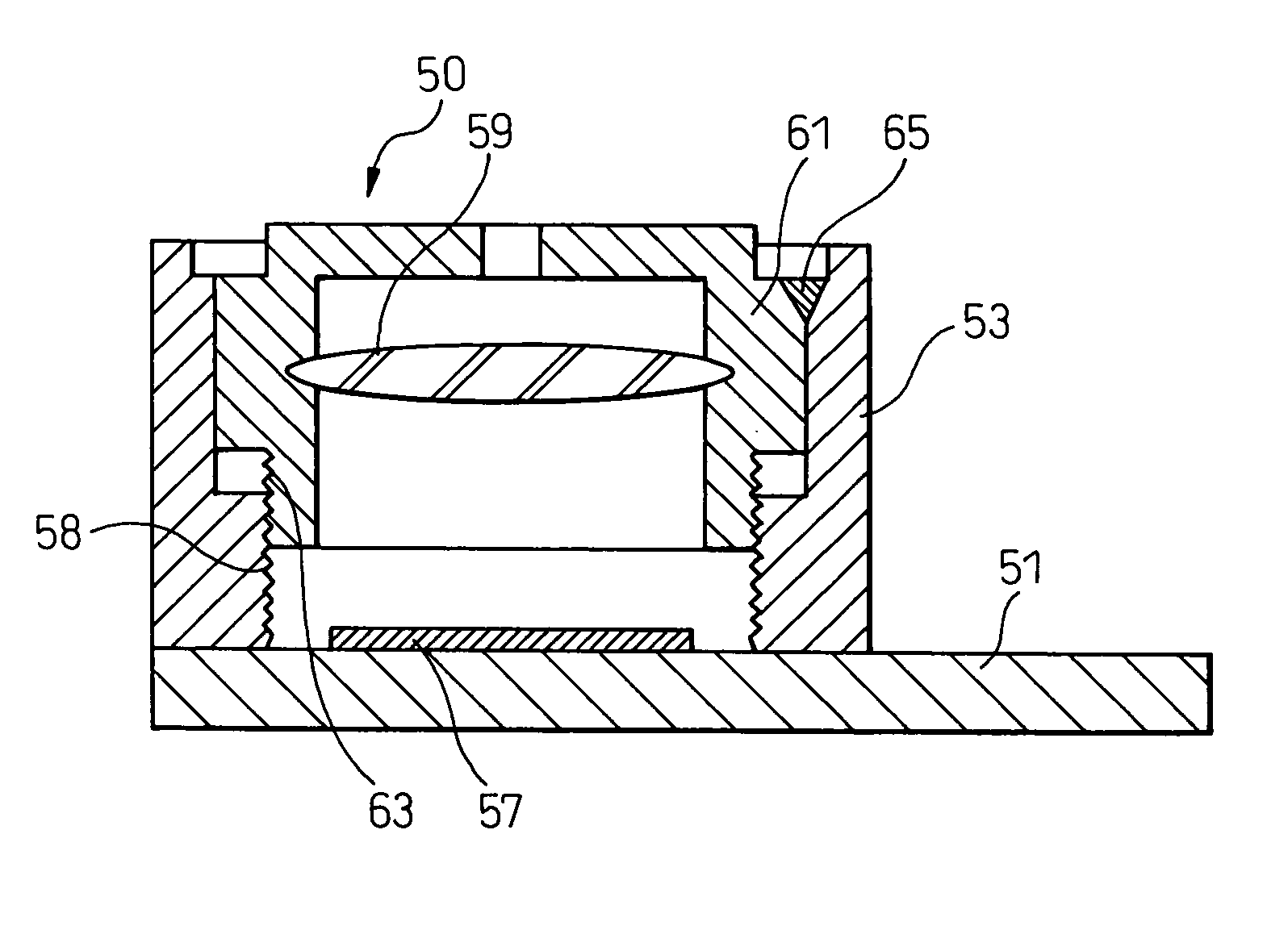
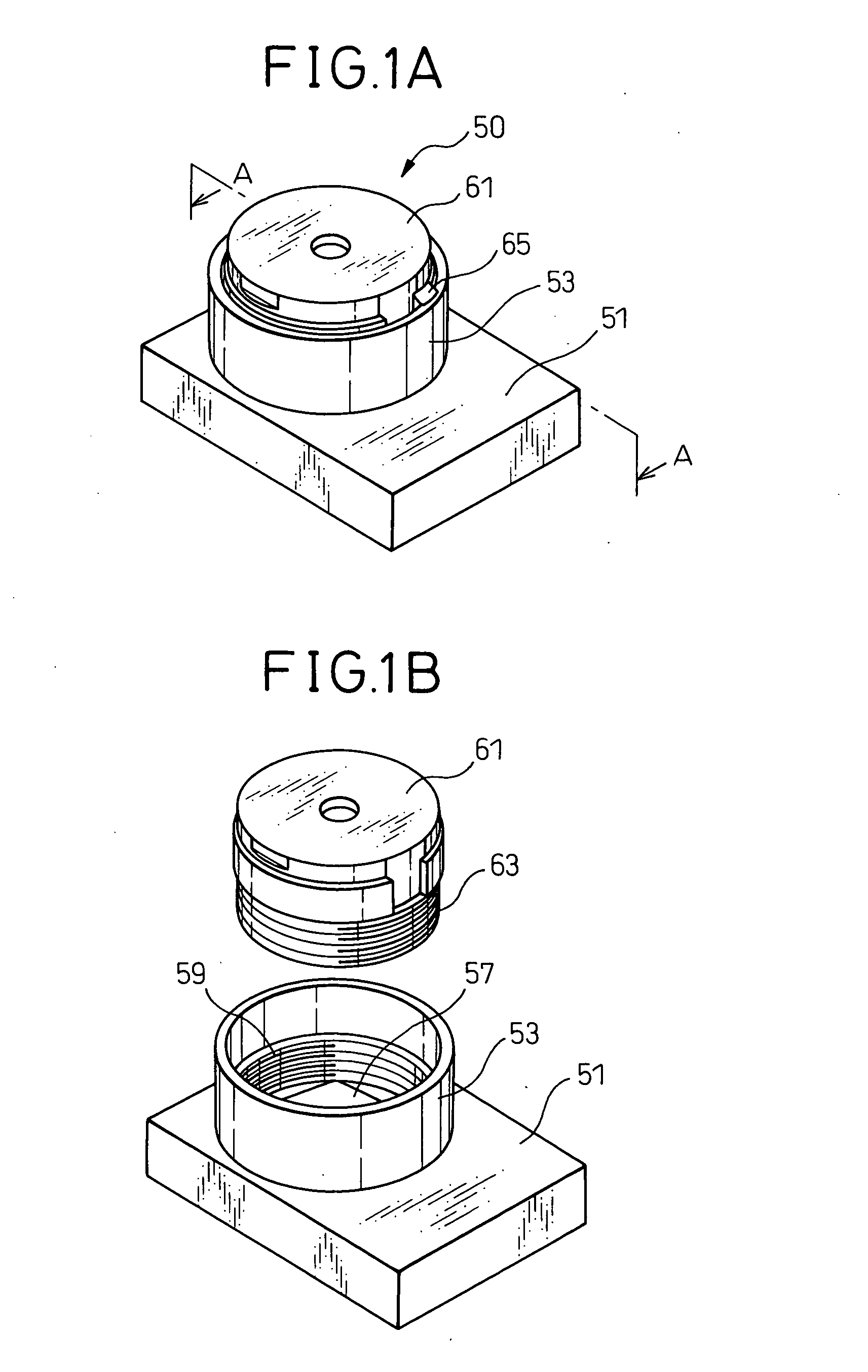
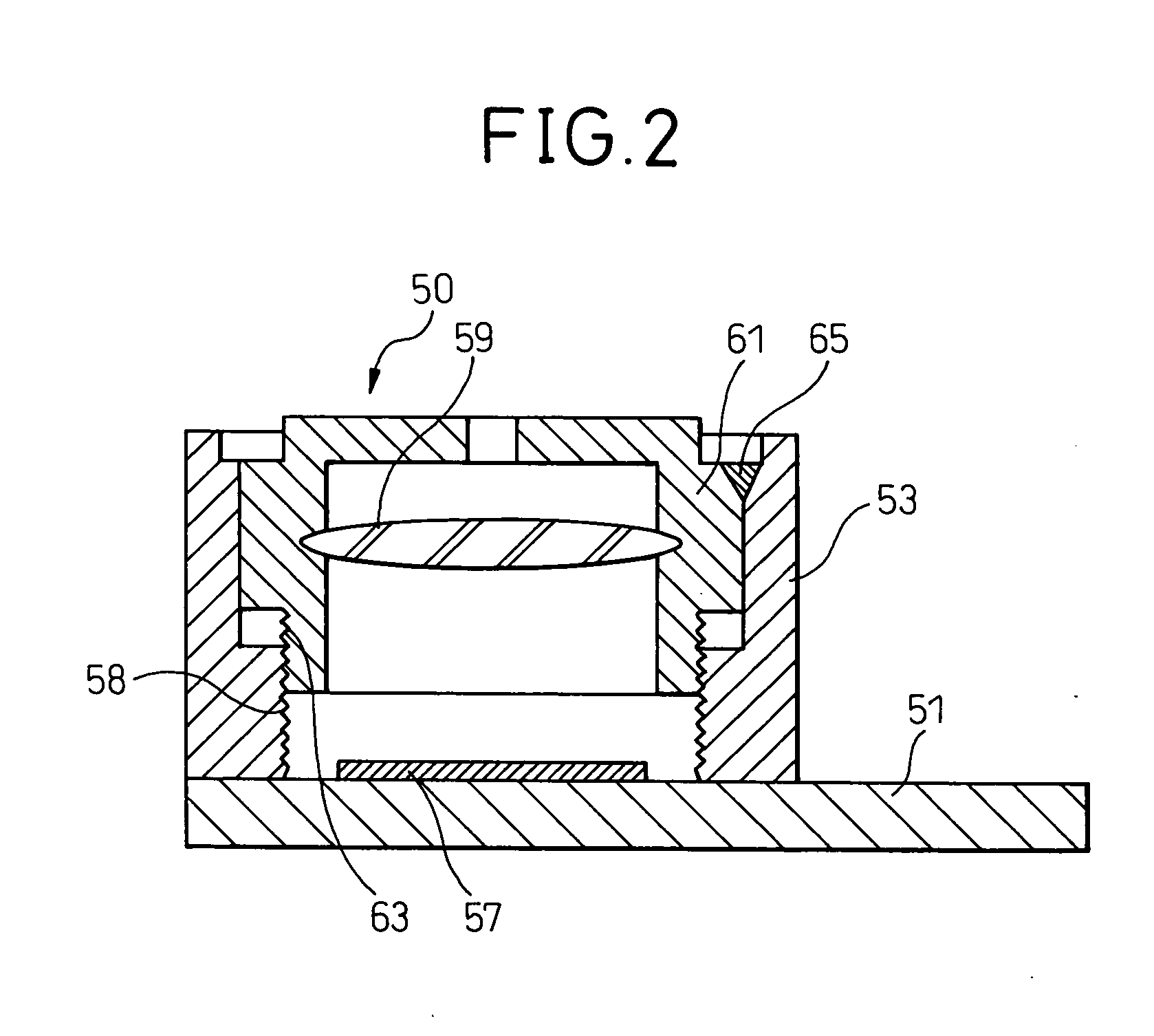
[0042] First, the imaging device 50 of this embodiment will be explained. FIGS. 1A and 1B are views of an imaging device of the present embodiment, wherein FIG. 1A is a perspective view and FIG. 1B is a disassembled perspective view, and FIG. 2 is sectional view of the configuration along the line A-A of FIG. 1A.

[0043] In these figures, a base 51 is provided with a cylindrical plastic barrel member 53. Inside the barrel member 53 and on the base 51 are provided a CCD, C-MOS sensor, or other imaging device 57. The inner circumference of the barrel member 53 is formed with a female thread 58.

[0044] The barrel member 53 is provided inside it with a plastic lens member 61. The lens member 61 is provided inside it with a condensing lens 59 for condensing light from a subject onto the imaging device 57. Further, the lens member 61 is f...


PUM

PropertyMeasurementUnit
temperatureaaaaaaaaaa
circumferenceaaaaaaaaaa
heat conductivityaaaaaaaaaa

Abstract

An imaging device including a base on which an imaging element is provided, a cylindrically shaped plastic lens member holding a condensing lens at the inside, and a plastic barrel member in which the lens member can move in the axial direction and provided above the imaging element, wherein the barrel member and the lens member are affixed by laser welding, a method of production of the same, and an imaging device holding mechanism used for that production.

Description

BACKGROUND OF THE INVENTION [0001] 1. Field of the Invention [0002] The present invention relates to an imaging device comprised of a base on which an imaging element is provided, a cylindrically shaped plastic lens member holding a condensing lens at the inside, and a plastic barrel member in which the lens member can move in the axial direction and provided on the imaging element, a method of production of the same, and an imaging device holding mechanism used for that production. [0003] 2. Description of the Related Art [0004] With digital equipment being made more sophisticated in function and smaller in size, utilization of image recording functions has been increasing. Along with this, small sized camera components, that is, imaging devices, are increasingly being built into that equipment. [0005] As such an imaging device, there is for example one of the configuration shown in FIGS. 9A and 9B. FIG. 9A is a perspective view, while FIG. 9B is a disassembled perspective view. In...

Claims


Application Information

Patent Timeline
Patent Type & Authority Applications(United States)
IPC IPC(8): B29C65/16G02B7/02B29C65/56B29C65/72B29L11/00H04N5/225
CPCB29C65/561B29C66/961B29C66/54B29C66/90B29C66/91216B29C66/91221B29L2011/0016H04N5/2254B29C66/21B29C65/1638B29C65/1648B29C65/1687B29C66/91411B29C66/91641B29C66/91212B29C65/72B29C65/1629B29C66/1162H04N23/55
Inventor MATSUSHITA, NAOHISAIIDA, SUSUMU
Owner FUJITSU LTD
Why Eureka
Try Eureka