Flying height tester and flying height test method

Inactive Publication Date: 2005-06-02
INT MFG & ENG SERVICES
View PDF3 Cites 6 Cited by
  • Summary
  • Abstract
  • Description
  • Claims
  • Application Information

AI Technical Summary

Benefits of technology

[0038] Furthermore, the pseudo-zero state of the flying height can be made stably and easily under no influence of crown or camber of the magnetic head because the pseudo-zero

Problems solved by technology

Therefore, it is difficult to secure the maximum flying height value necessary for obtaining the light intensity data I′ for calibration even if the magnetic head flies under different load conditions as well as a single load condition.
Theref

Method used


Image

  • Flying height tester and flying height test method
  • Flying height tester and flying height test method
  • Flying height tester and flying height test method

Examples


Embodiment Construction

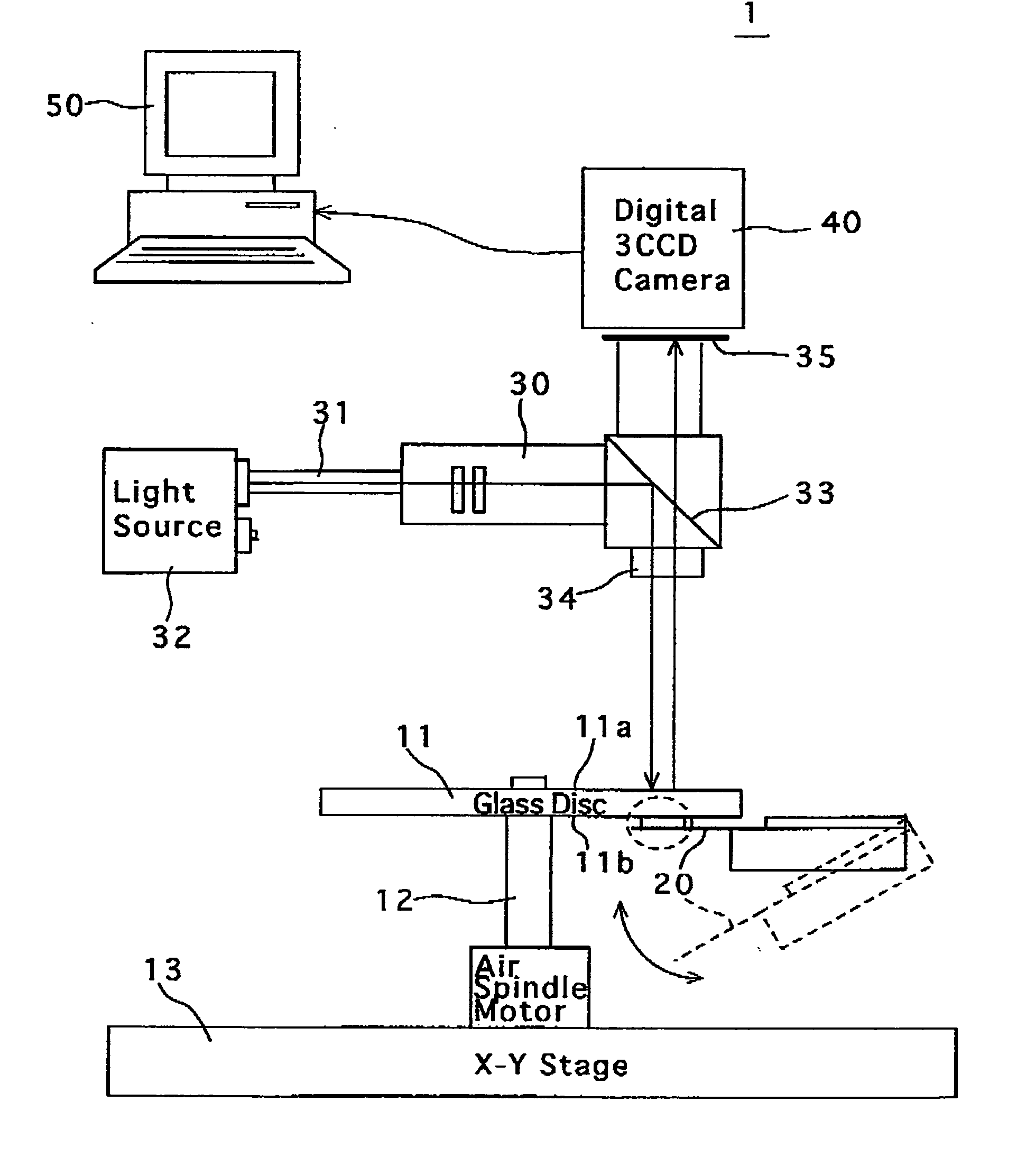
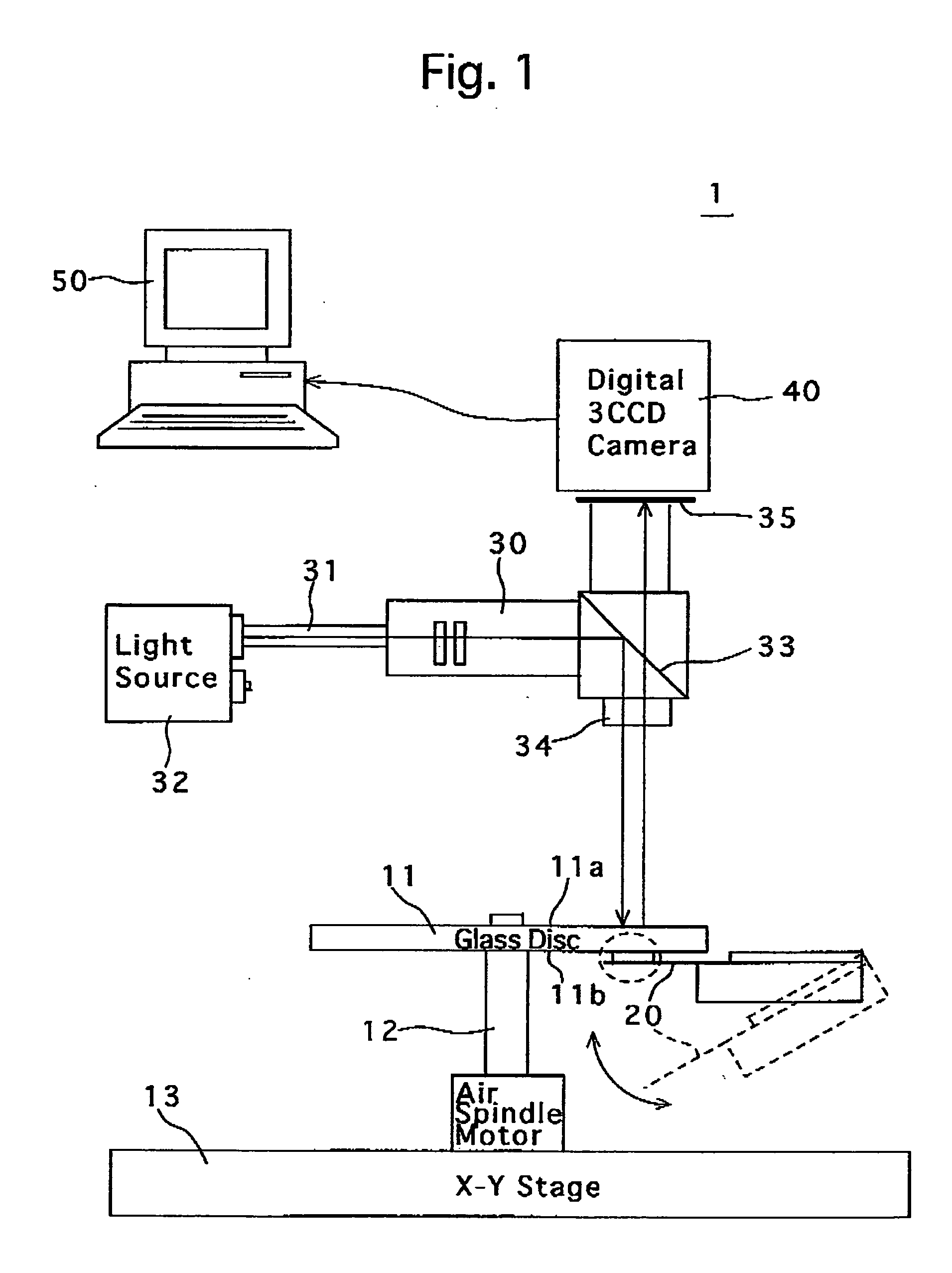
[0051]FIG. 1 is a schematic diagram of an embodiment of a flying height tester 1 according to the present invention. The flying height tester 1 is provided with a rotatable transparent glass disc 11 as a substitute for a magnetic disc (magnetic recording media), and operates to measure a flying height of a magnetic head slider 20 which is biased in a direction to come into pressing contact with a lower surface 11b of the glass disc 11 from the lower side of the glass disc 11 by a slight spring force while the glass disc 11 is spinning. In this particular embodiment of the flying height tester 1, a distance between a surface (the lower surface 11b) of the glass disc 11 and a slider surface of the magnetic head slider 20 is measured as the flying height of the magnetic head slider 20. Note that the slider surface of the magnetic head slider 20 refers to a mirror-finished air bearing surface (ABS) having a predetermined shape (pattern) in plane view to which the magnetic head is operab...


PUM


Abstract

A flying height tester includes a glass disc facing a magnetic head slider under test; an optical system for guiding light to the glass disc so that multiple reflections of light occur between the glass disc and the magnetic head slider; a light sensor receiving reflection light from the glass disc to output light intensity data; and a processor which calculates back the flying height based on an output function of the light sensor. The processor calibrates intensity gain data and intensity offset data of the output function using the data obtained in a pseudo-zero state of the flying height. This pseudo-zero state is obtained by applying an index matching liquid between a first-calibration magnetic head slider, having the same optical constants as the magnetic head slider under test, and the glass disc, the index matching liquid having a refractive index identical to the glass disc.

Description

CROSS REFERENCE TO RELATED APPLICATION [0001] The present application is related to and claims priority of the following Japanese Patent Application No.2003-390054 filed on Nov. 20, 2003. BACKGROUND OF THE INVENTION [0002] 1. Field of the Invention [0003] The present invention relates to a flying height tester and a flying height test method which determines the flying height optically with the phenomenon of multiple reflections produced between a glass disc and a magnetic head slider. [0004] 2. Description of the Related Art [0005] The magnetic head (read / write head), which is an element of a magnetic read / write system, flies at a small air gap from the, surface of the spinning magnetic recording disc. The flying height of a magnetic head is usually tested using a flying height tester (FHT) in a form of a head gimbal assembly (HGA), according to the specifications thereof. [0006] Various types of flying height testers have been developed. A particular type of flying height tester w...

Claims


Application Information

Patent Timeline
IPC IPC(8): G01B11/14G11B5/455G11B5/60
CPCG01B11/14G11B5/6005G11B5/455G11B5/4555G11B5/5534G11B5/6052
Inventor NOZU, TAKASHINOZU, YUKAHISANO, TEIJI
Owner INT MFG & ENG SERVICES
Why Eureka
Try Eureka