Measuring method and apparatus using shearing interferometry, exposure method and apparatus using the same, and device manufacturing method

a technology of shearing interferometry and measurement method, applied in the field of measuring method and apparatus, can solve the problems of increasing noise influence, increasing errors in wave number components having periods close,

Inactive Publication Date: 2005-06-02
CANON KK
View PDF6 Cites 6 Cited by
  • Summary
  • Abstract
  • Description
  • Claims
  • Application Information

AI Technical Summary

Benefits of technology

[0005] Accordingly, it is an illustrative object of the present invention to provide a measuring method and apparatus for measuring a wave front of a target optical system in a wide frequency-component range that covers a higher frequency component than the conventional ones using the shearing interferometry, an exposure method and apparatus using them, and a device manufacturing method.

Problems solved by technology

Therefore, a mere integration of the differential wave front causes increased errors in wave number components having periods close to the shearing amount.
However, in turn, the noise influence becomes problematic due to the reduced output of the differential wave front measured by the interferometer.

Method used


Image

  • Measuring method and apparatus using shearing interferometry, exposure method and apparatus using the same, and device manufacturing method
  • Measuring method and apparatus using shearing interferometry, exposure method and apparatus using the same, and device manufacturing method
  • Measuring method and apparatus using shearing interferometry, exposure method and apparatus using the same, and device manufacturing method

Examples


Embodiment Construction

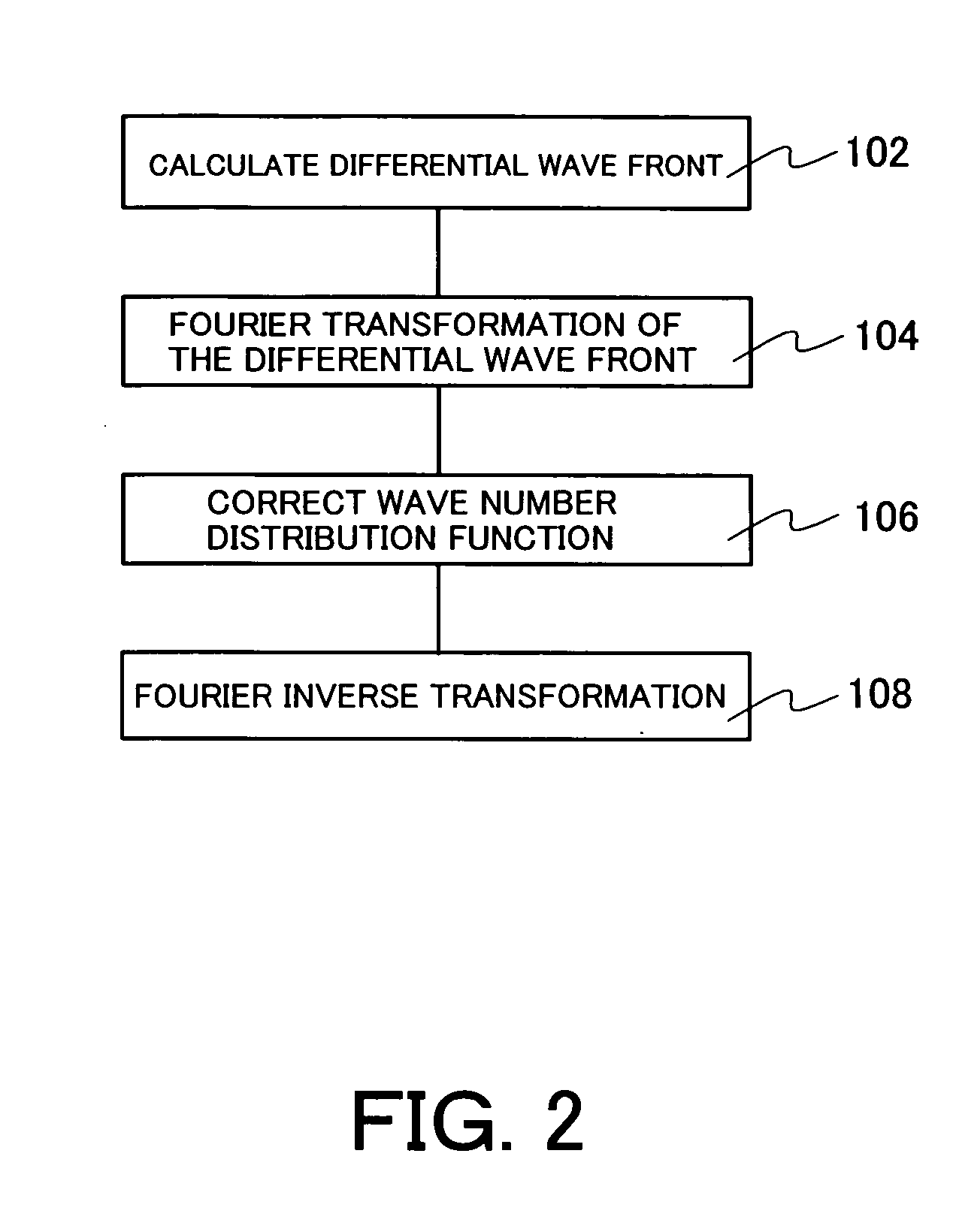
[0021] The instant inventor has discovered that a high-frequency component is correctly calculated by calculating a wave number distribution function through a Fourier transformation to a differential wave front, multiplying the wave number distribution function by a correction coefficient, and executing an inverse Fourier transformation to the result, instead of merely integrating the differential wave front. A description will now be given of the wave front calculating method in the measuring method of the instant embodiment.

[0022] First, a correction coefficient is calculated based on a result of a relationship between a wave number distribution function of a target wave front and a wave number distribution function of a differential wave front. The target wave front is W(x, y), and its Fourier transformation F(α, β) is a spatial wave number distribution function of W(x, y), where α and β are wave numbers in x and y directions. W(x, y) is an inverse Fourier transformation in vie...


PUM

PropertyMeasurementUnit
wavelengthaaaaaaaaaa
grating constantsaaaaaaaaaa
optical axisaaaaaaaaaa

Abstract

A measuring method for measuring wave front of light, which passed through a target optical system includes the steps of, generating an interference fringe using a shearing interference with light that passes a target optical system, calculating a differential wave front between a first wave front of the light that passes the target optical system and a second wave front made by offsetting the first wave front by a predetermined amount in a predetermined direction, and correcting the differential wave front based on the predetermined amount and the wave number in the predetermined direction.

Description

BACKGROUND OF THE INVENTION [0001] The present invention relates generally to measuring method and apparatus, and more particularly to a measuring method and apparatus that uses the shearing interferometry to measure a wave front aberration of a target optical system, such as a projection optical system that transfers a mask pattern onto an object, and an exposure method and apparatus using the measuring method and apparatus. The inventive measuring method and apparatus is suitable, for example, for a measurement of a projection optical system in an exposure apparatus that utilizes the extreme ultraviolet (“EUV”) light. [0002] A projection exposure apparatus is used to transfer a pattern on a mask (or a reticle) onto an object to be exposed in manufacturing semiconductor devices, etc. in the photolithography process. This exposure apparatus is required to transfer the pattern on the reticle onto the object precisely at a predetermined magnification. For this purpose, it is important...

Claims


Application Information

Patent Timeline
Patent Type & Authority Applications(United States)
IPC IPC(8): G01B9/02G21K1/06G01J9/02G01M11/02G03F7/20G21K5/00G21K5/02H01L21/027
CPCG01J9/0215G03F7/706G03F7/70266
Inventor OUCHI, CHIDANE
Owner CANON KK
Why Eureka
Try Eureka