Laminated common mode choke coil and high frequency component

a common mode choke coil and high frequency technology, applied in the direction of basic electric elements, fixed transformers or mutual inductances, inductances, etc., can solve the problems of insufficient coupling value, hard to ensure symmetry, and deterioration of the removal of common mode noise, so as to achieve excellent symmetry, reduce impedance, and increase the coupling degree of primary coil and secondary coil.

Active Publication Date: 2016-01-05
MURATA MFG CO LTD
View PDF9 Cites 2 Cited by
  • Summary
  • Abstract
  • Description
  • Claims
  • Application Information

AI Technical Summary

Benefits of technology

[0012]The present invention has been made to solve the problems, and an object thereof is to provide a small-sized common mode choke coil having a small loss of a normal mode signal and high removability of a common mode noise, and a high frequency component including the same.
[0015]According to the present invention, the problem in the process (the forming of positional shift of the coil pattern, the stacking shift of the sheet or the like) and the structural problem (the problem in which the coupling amount of each coil and the ground conductor on the printed wiring board differs when they are provided on the printed wiring board) are hardly caused, and excellent symmetry can be ensured. Moreover, a degree of coupling of the primary coil and the secondary coil is increased. Therefore, a great inductance value is obtained for a common mode signal so that an impedance is increased, and the inductance value is reduced for a normal mode signal so that the impedance is reduced. Accordingly, it is possible to obtain a small-sized common mode choke coil having a small loss of the normal mode signal and high removability of a common mode noise, and a high frequency component including the same.

Problems solved by technology

In the case in which the primary coil and the secondary coil are arranged symmetrically in a lamination direction in a laminated element body, however, there is a problem.
When the coils are provided on a printed wiring board, moreover, it is hard to ensure symmetry thereof due to a structural problem.
If the symmetry of the two coils is lacking, removability of the common mode noise is deteriorated.
Moreover, a sufficient coupling value cannot be obtained between the primary coil and the secondary coil particularly in the high frequency band, and thus a loss of a normal mode signal tends to be increased.

Method used


Image

  • Laminated common mode choke coil and high frequency component
  • Laminated common mode choke coil and high frequency component
  • Laminated common mode choke coil and high frequency component

Examples


first embodiment

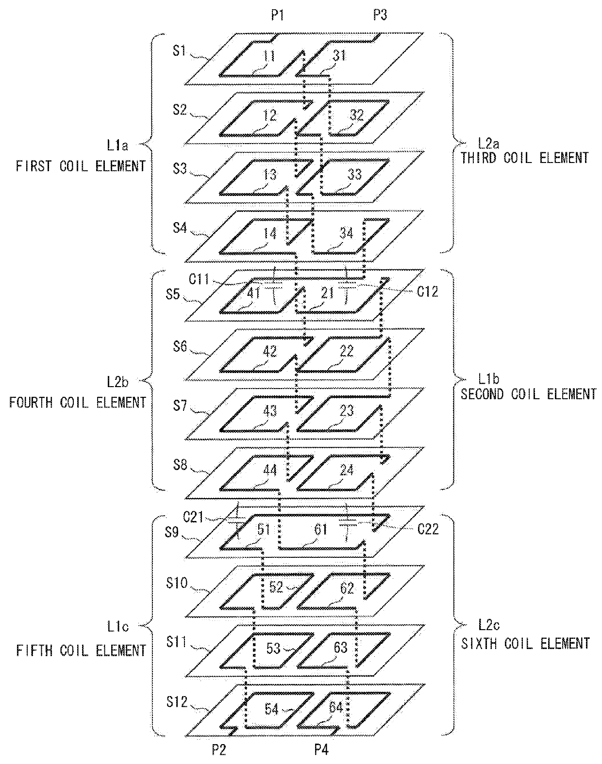
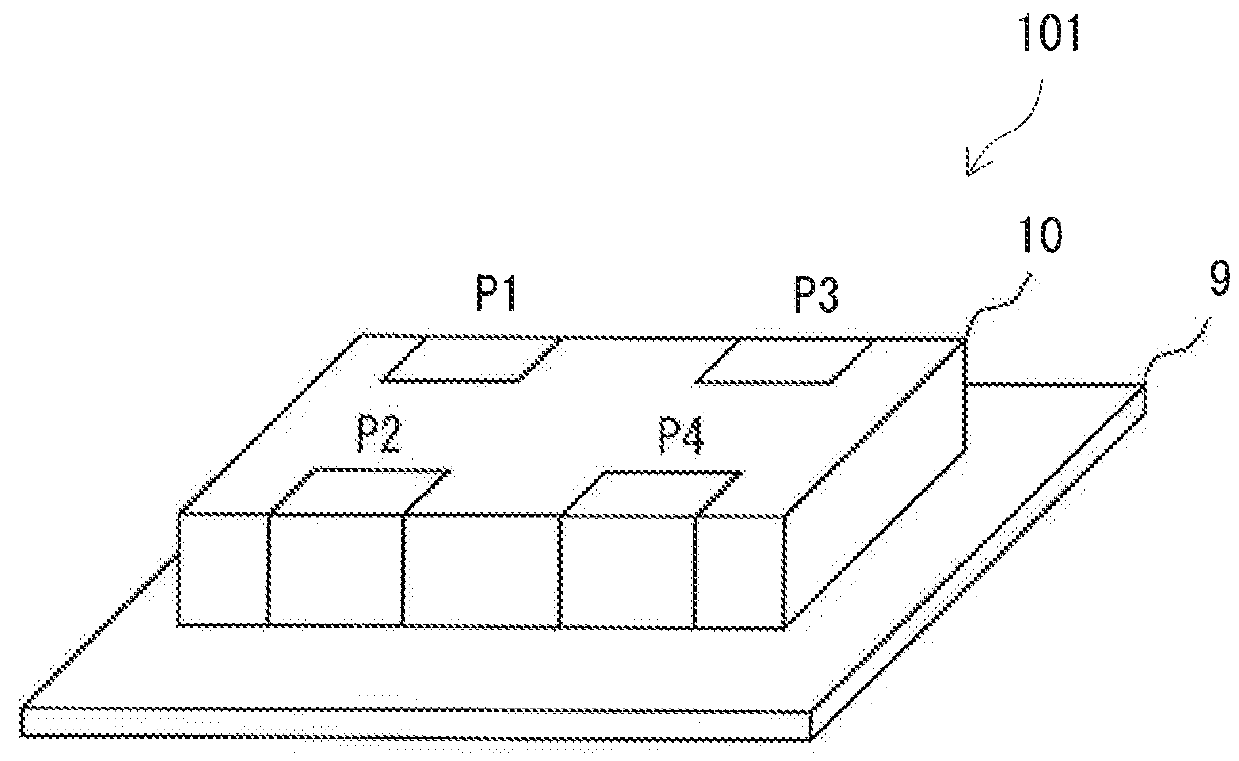
[0036]FIG. 1 is an exploded perspective view showing a common mode choke coil according to a first embodiment. FIG. 2 is a perspective view showing a state in which a common mode choke coil 101 is mounted on a printed wiring board 9 according to the first embodiment.

[0037]The common mode choke coil 101 is a laminated common mode choke coil having a laminated element body 10 obtained by laminating a plurality of base material layers including base material layers S1 to S12 and a primary coil and a secondary coil which are provided on the laminated element body and are coupled to each other.

[0038]As shown in FIG. 1, conductor patterns are formed on the base material layers S1 to S12. Conductor patterns 11 to 14, conductor patterns 21 to 24 and conductor patterns 51 to 54 are formed on the base material layers S1 to S4, the base material layers S5 to S8 and the base material layers S9 to S12, respectively. Moreover, conductor patterns 31 to 34, conductor patterns 41 to 44 and conductor...

second embodiment

[0060]FIG. 7 is an exploded perspective view showing a common mode choke coil according to a second embodiment. FIG. 8 is a perspective view showing a common mode choke coil 102 according to the second embodiment.

[0061]The common mode choke coil 102 is a laminated common mode choke coil having a laminated element body 10 obtained by laminating a plurality of base material layers including base material layers S1 to S8 and a primary coil and a secondary coil which are provided on the laminated element body and are coupled to each other.

[0062]As shown in FIG. 7, conductor patterns are formed on the base material layers S1 to S8. Conductor patterns 11 to 14 and conductor patterns 21 to 24 are formed on the base material layers S1 to S4 and the base material layers S5 to S8, respectively. Moreover, conductor patterns 31 to 34 and conductor patterns 41 to 44 are formed on the base material layers S1 to S4 and the base material layers S5 to S8, respectively. Dashed lines extending in a ve...

third embodiment

[0073]FIG. 11 is an exploded perspective view showing a high frequency component according to a third embodiment. FIG. 12 is a perspective view showing a high frequency component 103 according to the third embodiment.

[0074]The high frequency component 103 includes a laminated common mode choke coil having a laminated element body 10 obtained by laminating a plurality of base material layers including base material layers S1 to S9 and a primary coil and a secondary coil which are provided on the laminated element body and are coupled to each other.

[0075]As shown in FIG. 11, conductor patterns are formed on the base material layers S1 to S9. Conductor patterns 11 to 13, conductor patterns 21 to 24 and conductor patterns 51 to 53 are formed on the base material layers S1 to S3, the base material layers S3 to S6 and the base material layers S6 to S8, respectively. Moreover, conductor patterns 31 to 33, conductor patterns 41 and 42 and conductor patterns 61 to 63 are formed on the base m...


PUM

PropertyMeasurementUnit
thicknessaaaaaaaaaa
thicknessaaaaaaaaaa
thicknessaaaaaaaaaa

Abstract

A primary coil is configured by series connection of a first coil element (L1a), a second coil element (L1b) and a fifth coil element (L1c), and a secondary coil is configured by series connection of a third coil element (L2a), a fourth coil element (L2b) and a sixth coil element (L2c). The coil elements (L1a, L2b, L1c) are disposed coaxially and the coil elements (L2a, L1b, L2c) are also disposed coaxially. The respective coil elements (L1a, L1b, L1c) of the primary coil and the respective coil elements (L2a, L2b, L2c) of the secondary coil are disposed adjacently in a layer direction of a base material layer, respectively. The coil elements (L1a, L1b, L1c, L2a, L2b, L2c) are connected in such a manner that a magnetic field in the same direction is generated in all of the coil elements (L1a, L1b, L1c, L2a, L2b, L2c) when common mode current flows.

Description

CROSS-REFERENCE TO RELATED APPLICATIONS[0001]The present application claims priority to JP2011-189125 and JP2011-257519 which are herein incorporated by reference.TECHNICAL FIELD[0002]The present invention relates to a laminated common mode choke coil to be applied to a transmission line for a high frequency signal, and a high frequency component including the same.BACKGROUND ART[0003]For example, a high speed interface such as a USB or an HDMI uses a “differential transmission system” for transmitting signals having different phases by 180° through a pair of signal lines. Since radiation noises or external noises are offset in a balanced line, the differential transmission system is hardly influenced by these noises. However, in actuality, noise current in a common mode based on asymmetry of a signal line for a high speed interface is generated particularly in the signal line. For this reason, a common mode choke coil is used in order to control the common mode noise.[0004]Usually,...

Claims


Application Information

Patent Timeline
Patent Type & Authority Patents(United States)
IPC IPC(8): H01F5/00H01F27/24H01F17/00H01F19/04
CPCH01F5/003H01F17/0013H01F19/04H01F2017/0093
Inventor KATO, NOBORU
Owner MURATA MFG CO LTD
Why Eureka
Try Eureka