

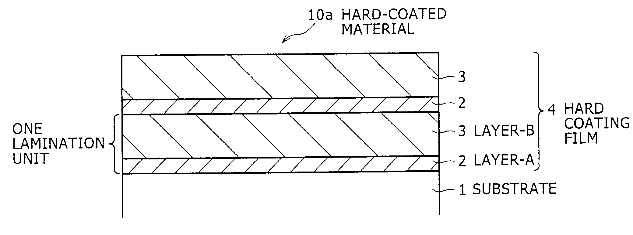
Material with hard coating film formed on substrate surface thereof
a technology of substrate surface and hard coating, which is applied in the direction of superimposed coating process, natural mineral layered products, instruments, etc., can solve the problems of significant wear period of time to remove, and poor wear resistance of the hard coating film, etc., to achieve excellent wear resistance and enhance the effect of film removal
- Summary
- Abstract
- Description
- Claims
- Application Information
AI Technical Summary
Benefits of technology
Problems solved by technology
Method used
Image

Examples
example 1
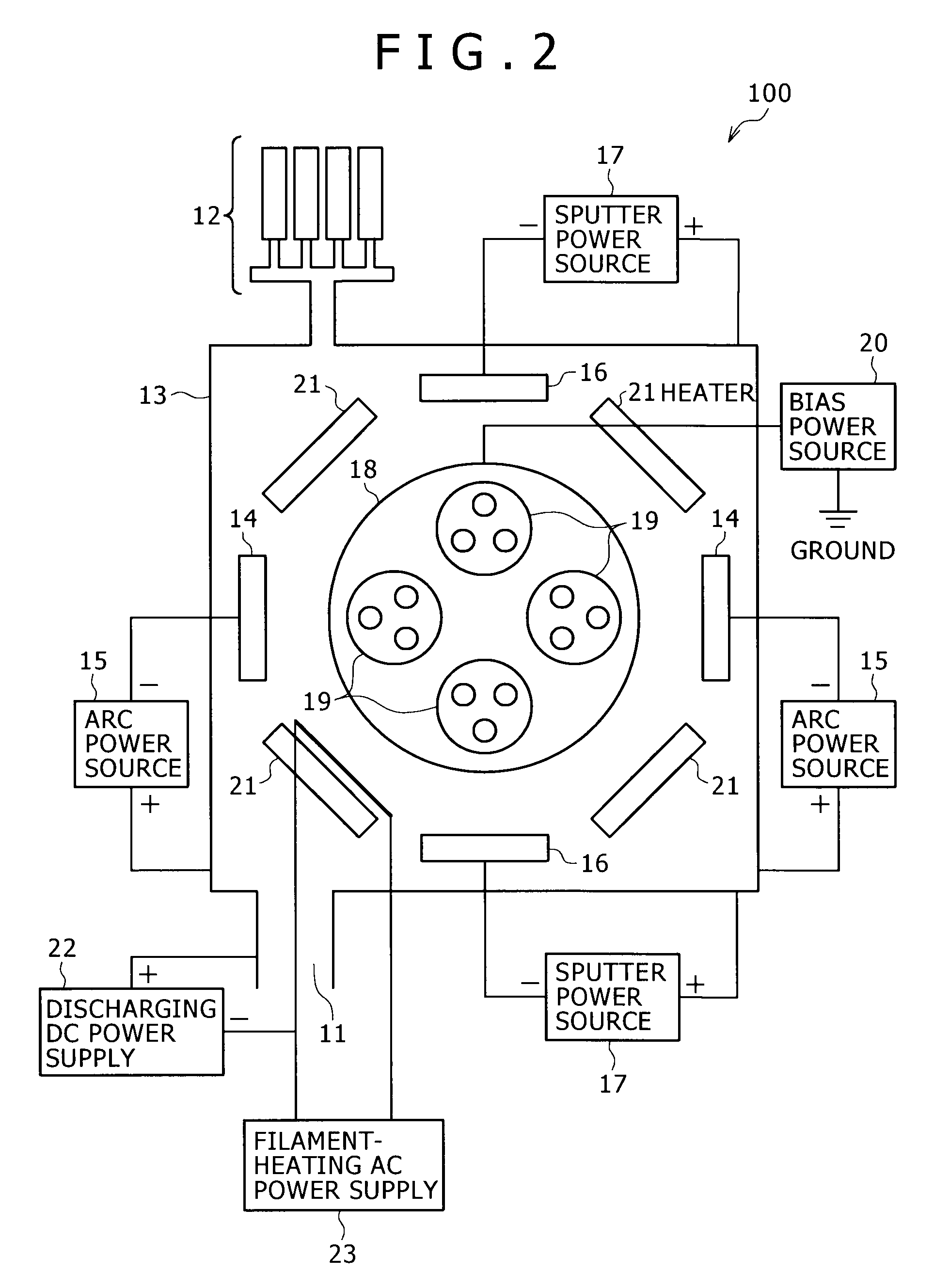
[0072]Each target made of alloy or metal having a predetermined component composition was mounted on each cathode of the hybrid-type film forming apparatus, and a mirror-finished JIS-SKD11 substrate (object under processing) was set on each substrate holding mount equipped on the substrate stage. Then, the chamber was evacuated (below 1×10⁻³ Pa) to provide a vacuum state in the inside thereof. Thereafter, the substrate was heated up to approximately 400° C. by the heater in the chamber, and sputter cleaning with Ar ions was carried by using the sputter evaporation source to form a layer-A. Then, arc ion plating was carried out by using the arc evaporation source to form a layer-B. The conditions of arc ion plating were as follows: A target having a size of ø100 mm was used, an arc current of 150 A was applied, and an atmosphere of N2 gas was provided at a total pressure of 4 Pa. In the case of inclusion of carbon, an atmosphere of CH4 gas or mixture gas of N2 and CH4 was provided. I...
example 2
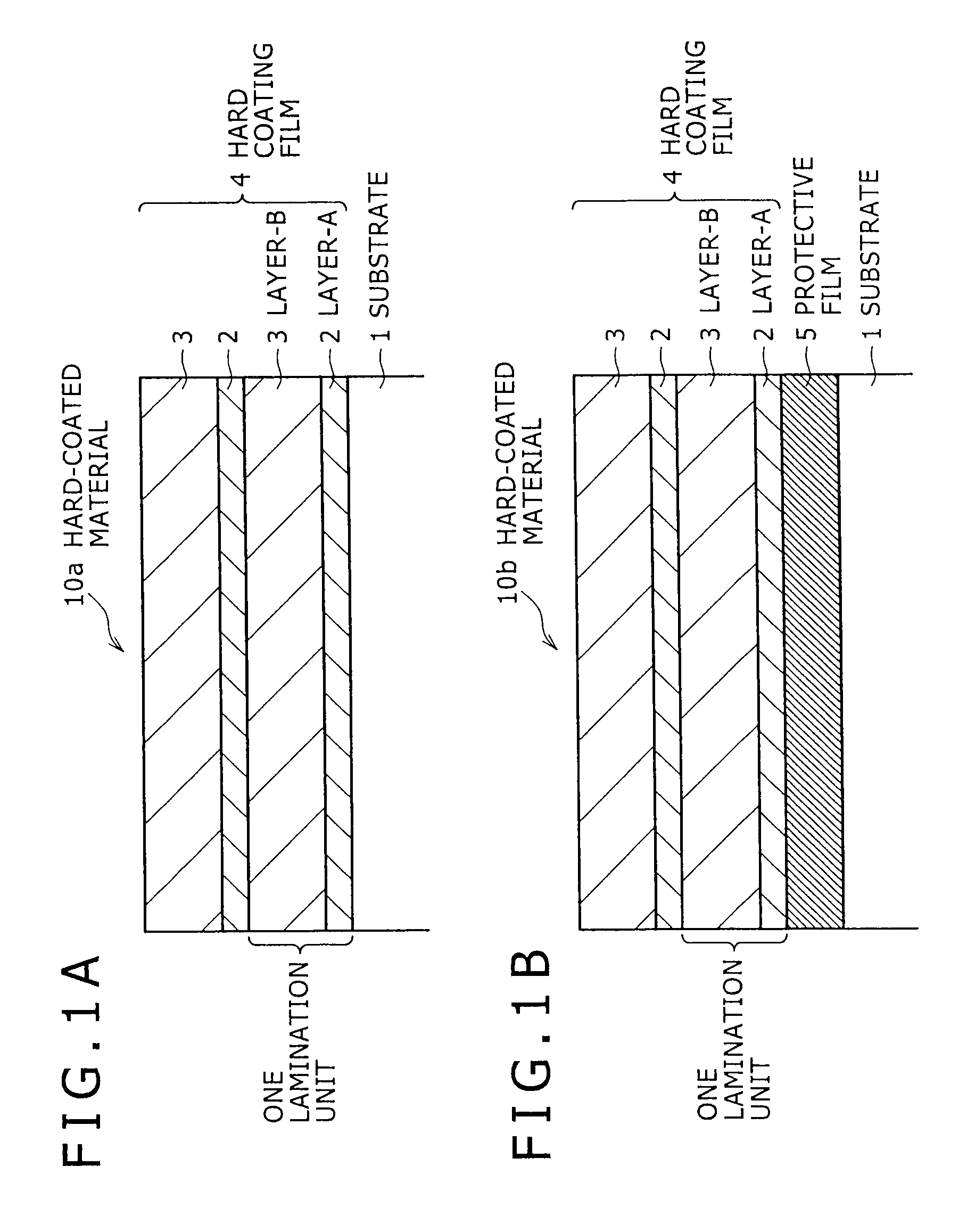
[0093]The degree of effect of provision of the protective film was examined in Example 2.
[0094]In the same manner as in Example 1, a coating film was formed on each substrate. A mirror-finished JIS-SKD11 substrate (indicated as SKD11 in TABLE 2) or a cemented carbide substrate (indicated as CEMENTED CARBIDE in TABLE 2) was used in Example 2. Except some samples, a protective film (CrN film) having a predetermined thickness was formed between the substrate and the coating film. For forming the protective film, a Cr target was employed, and in an atmosphere of N2 gas, arc ion plating was carried out.
[0095]After completion of the film formation mentioned above, the metallic component compositions of the coating film and protective film were examined, and also the degree of substrate protection was evaluated.
[0096]The composition of metallic component elements in each of the layer-A and layer-B was measured by using an EPMA (Electron Probe Micro Analyzer).
[0097]Before and after film rem...
PUM
| Property | Measurement | Unit |
|---|---|---|
| total thickness | aaaaa | aaaaa |
| total thickness | aaaaa | aaaaa |
| total thickness | aaaaa | aaaaa |
Abstract
Description
Claims
Application Information