Apparatus for and method of measuring image

a technology of optical image and measuring apparatus, applied in the direction of optical apparatus testing, television systems, instruments, etc., can solve the problems of difficult to acquire information about an area, take a long time for acquiring an image frame, and drive errors according to the shape of the object p

Active Publication Date: 2012-04-10
INTEKPLUS
View PDF14 Cites 1 Cited by
  • Summary
  • Abstract
  • Description
  • Claims
  • Application Information

AI Technical Summary

Benefits of technology

[0018]It is a further object of the present invention to provide an image measuring apparatus for removing noise generated during the measurement and a high frequency component generated from an edge, and a method thereof.

Problems solved by technology

Moreover, in a case of using a contact-type surface illuminance measuring apparatus using a contact probe, a tip of the contact probe generates fine scratches on a surface of an object to be measured and it is hard to acquire information about an area thereof.
Therefore, it takes a long time for acquiring an image frame.
Moreover, since the piezoelectric actuator controller and the camera for capturing an image are driven at constant speed, a driving error may occur according to the shape of the object P.

Method used


Image

  • Apparatus for and method of measuring image
  • Apparatus for and method of measuring image
  • Apparatus for and method of measuring image

Examples


Embodiment Construction

[0027]The embodiments of the present invention will be described in detail with reference to accompanying drawings such that those skilled in the art may fully understand and achieve the concept of the present invention.

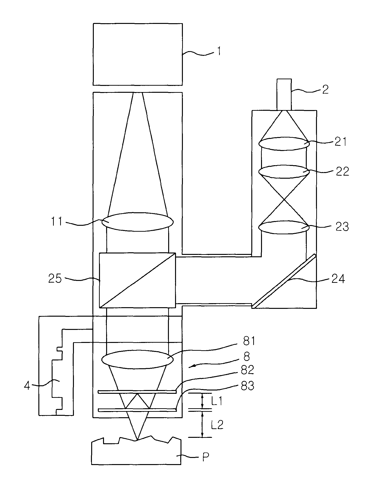
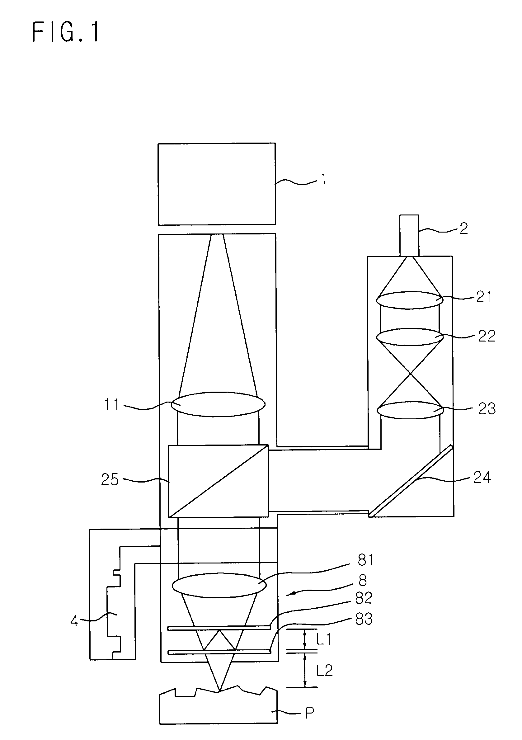
[0028]FIG. 1 is a view illustrating a configuration of an optical system of an image measuring apparatus according to the present invention. A basic principle of a three-dimensional surface illuminance measuring method using WSI will be described with reference to FIG. 1 as follows. White light emitted from a lamp 2 enters an optical splitter 25 via a first lens 21, a second lens 22, a third lens 23, and a reflecting mirror 24, the white light reflected by the optical splitter 25 is focused by a lens 81, and the focused white light is projected on an object P to be measured via an optical splitter 83.

[0029]In the optical splitter 83 of an interferometer, the white light is split into a white light to be projected on the object P and a white light to be projected on a...


PUM


Abstract

An image measuring apparatus for enhancing an accuracy of an image captured by an optical system and a method thereof are disclosed. The apparatus includes a CCD camera for capturing the object and outputting the captured image, a lamp for generating white light to illuminate a capturing area of the object, an illumination controller for controlling the lamp to be turned on, a piezoelectric actuator for controlling a minute height of the optical system with respect to the object, an image capturing device for acquiring the image captured by the CCD camera, a driving signal generator for outputting a driving signal to the illumination controller and the piezoelectric actuator when an enable signal is generated from the CCD camera, and an image signal processor for estimating height information of the object from data transmitted from the image capturing unit.

Description

BACKGROUND OF THE INVENTION[0001]1. Field of the Invention[0002]The present invention relates to an optical image measuring apparatus and a method of optically measuring an image, and particularly to, an image measuring apparatus for enhancing an accuracy of an image captured by an optical system and a method thereof.[0003]2. Description of the Related Art[0004]Electronic and mechanical components are vigorously being required to be made smaller and more accurate, and in order to check processing and manufacturing statuses of the small electronic and mechanical components, their sizes, shapes, and surface illuminance must be measured very precisely.[0005]For example, sizes, shapes, laser marked statuses, and surface illuminance of an electronic component, that is, a semiconductor wafer and a micro-pattern of an integrated circuit fabricated on the semiconductor wafer cannot be measured by a conventional contact-type measuring apparatus. Moreover, in a case of using a contact-type su...

Claims


Application Information

Patent Timeline
Patent Type & Authority Patents(United States)
IPC IPC(8): G06K9/20
CPCG01B9/04G01B9/0209G01B11/24G01M11/0271G01N2021/0181G06T7/0004
Inventor LEE, SANG-YOONKANG, MIN-GULIM, SSANG-GUN
Owner INTEKPLUS
Why Eureka
Try Eureka