Endoscope

Active Publication Date: 2017-03-23
OLYMPUS CORP
View PDF6 Cites 2 Cited by
  • Summary
  • Abstract
  • Description
  • Claims
  • Application Information

AI Technical Summary

Benefits of technology

The present invention provides an endoscope that can enhance the high frequency component of an image pickup signal using a high frequency component enhancement circuit of a processor. The endoscope includes an image pickup device at the distal end of its insertion portion, an A / D converting portion, and a cable for transmitting the digital image pickup signal. An inverse characteristic filter is provided at the other end of the cable to equalize the frequency characteristics of the high frequency component enhancement circuit. The technical effect of this invention is to improve the quality of the optical image of the subject being examined and provide a clear and accurate image for diagnosis and treatment purposes.

Problems solved by technology

In an endoscope of this kind, it is difficult to appropriately transmit a signal output from the CCD image sensor arranged at a distal end of an insertion portion of the endoscope because of reasons that a cable connecting the image pickup device arranged on a distal end portion and the processor is relatively long, that a diameter of the cable is restricted in order to realize reduction in a diameter of the insertion portion of the endoscope, and so on.

Method used


Image

  • Endoscope
  • Endoscope
  • Endoscope

Examples


first embodiment

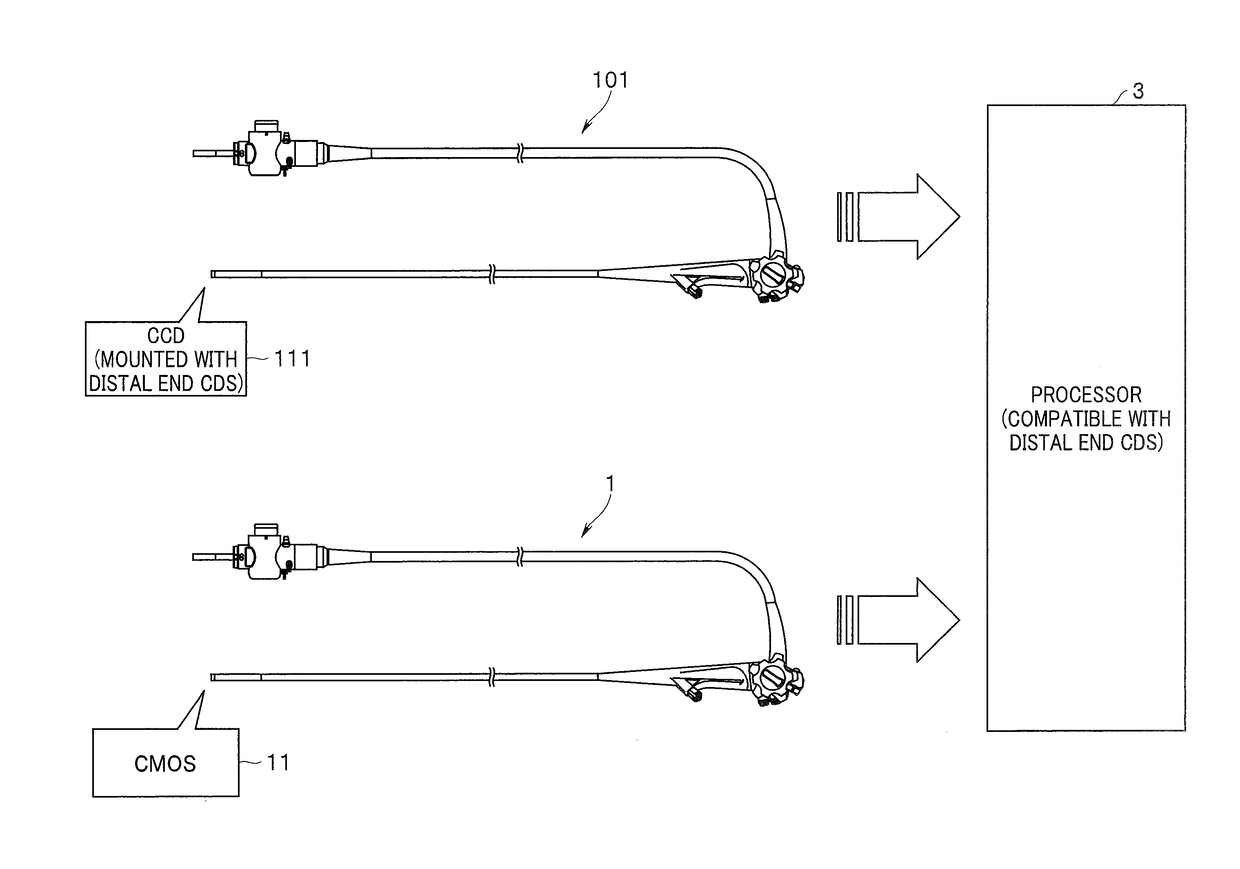
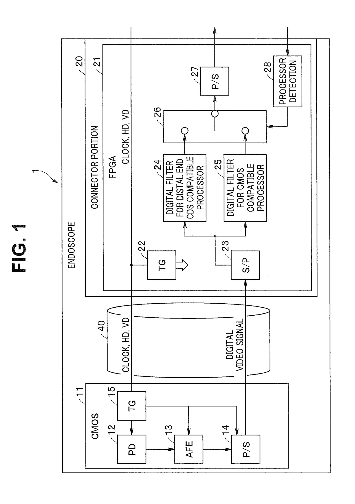
[0028]As shown in FIG. 1, an endoscope 1, which is the present invention, is provided with a CMOS image sensor 11 provided at a distal end of an insertion portion to be inserted into a subject and configured to pick up an optical image of the subject and output a predetermined digital image pickup signal; a cable 40 connected to the CMOS image sensor 11 and configured to transmit the digital image pickup signal; and a connector portion 20 connected to a processor as a signal processing apparatus configured to perform predetermined signal processing (details are to be described later).

[0029]The CMOS image sensor 11 is configured including: a timing generator (TG) 15 configured to generate a clock signal, a horizontal synchronization signal HD and a vertical synchronization signal VD fitted to operation specifications of the CMOS image sensor 11 and pulses for various signal processing, based on a predetermined clock signal and synchronization signals HD, VD transmitted from a clock s...

second embodiment

[0077]Next, the present invention will be described.

[0078]FIG. 11 is a diagram showing a configuration when an endoscope of the second embodiment of the present invention is connected to the distal end CDS compatible processor; and FIG. 12 is a diagram showing a configuration when the endoscope of the second embodiment is connected to the CMOS compatible processor. Furthermore, FIG. 13 is a flowchart showing operation of the digital filter processing in the endoscope of the second embodiment.

[0079]A basic configuration of the endoscope system of the present second embodiment is similar to that of the first embodiment, and only a partial configuration inside the FPGA 21 in the connector portion 20 is different. Therefore, only the difference from the first embodiment will be described here, and description of common parts will be omitted.

[0080]In the first embodiment described above, the FPGA 21 is provided with the processor detection circuit 28 configured so that the signal route s...


PUM


Abstract

An endoscope is an endoscope connectable to a processor provided with a high frequency component enhancement circuit configured to perform, for an image pickup signal having an attenuated high frequency component, enhancement correction of the high frequency component, the endoscope including: a CMOS image sensor provided with an image pickup portion configured to pick up an optical image of a subject and generate an analog image pickup signal and an A / D converting portion configured to convert the analog image pickup signal to a digital image pickup signal and output the digital image pickup signal; a cable for transmitting the digital image pickup signal; and a filter having frequency characteristics equalizing frequency characteristics of the high frequency component enhancement circuit.

Description

CROSS REFERENCE TO RELATED APPLICATION[0001]This application is a continuation application of PCT / JP2015 / 075518 filed on Sep. 8, 2015 and claims benefit of Japanese Application No. 2014-246136 filed in Japan on Dec. 4, 2014, the entire contents of which are incorporated herein by this reference.BACKGROUND OF THE INVENTION[0002]1. Field of the Invention[0003]The present invention relates to an endoscope mounted with an image pickup device configured to output a digital signal as an image pickup signal.[0004]2. Description of the Related Art[0005]Conventionally, an endoscope provided with an image pickup device has been widely used in a medical field and an industrial field. Further, a technique of configuring an endoscope system in which a signal processing apparatus referred to as a processor and attachably and detachably connected to an endoscope is responsible for various signal processing related to the endoscope is also known.[0006]Further, recently, there is a tendency that, in...

Claims


Application Information

Patent Timeline
IPC IPC(8): H04N5/3745H04N7/10H04N5/268A61B1/00G06T5/20H04N7/18A61B1/05H04N5/225G02B23/24
CPCH04N5/37455H04N5/2253H04N7/10H04N5/268G02B23/2484H04N2005/2255H04N7/183A61B1/05A61B1/00112A61B1/00009G06T5/20A61B1/04A61B1/000095H04N23/54H04N25/772H04N23/555
Inventor OKAWA, FUMIYUKIHASHIMOTO, HIDENORIMATSUI, YASUNORI
Owner OLYMPUS CORP
Why Eureka
Try Eureka