Profile arrangement for jamming protection and injection mould

a technology of jamming protection and injection moulding, which is applied in the direction of doors, windows, electrical equipment, etc., can solve the problems of a significant cost factor in the profile arrangement, and achieve the effect of convenient manufacturing, easy installation process and positive retention at right angles to the sliding direction

Inactive Publication Date: 2005-06-02
MAYSER
View PDF24 Cites 28 Cited by
  • Summary
  • Abstract
  • Description
  • Claims
  • Application Information

AI Technical Summary

Benefits of technology

[0009] According to a further development of the invention, the web arrangement and the at least one slot are so positively matched to one another that a positive retention at right angles to the sliding direction is ensured. This ensures that the switching profile is not removed from the support profile and in particular not from the slot by forces and/or moments, which have no preponderant components in the sliding direction. This applies for as long as the slot or switching profile is not damaged or so considerably deformed that an anchoring in the slot can no longer be ensured. In this way it is possible to respect test standards, such as are used as a basis for motor vehicles or machine tools. These testing standards require the ensuring of specific shearing and/or tearing-out forces for the switching profile from the support profile.
[0010] According to a further development of the invention, the at least one plug-in profiling of the support profile is constructed as a locking recess...

Problems solved by technology

In order to ensure a good adhesion of the adhesive tape on the switching profile and the support profile, it is necessary to carry out preliminary work such as cleaning pr...

Method used


Image

  • Profile arrangement for jamming protection and injection mould
  • Profile arrangement for jamming protection and injection mould
  • Profile arrangement for jamming protection and injection mould

Examples


Embodiment Construction

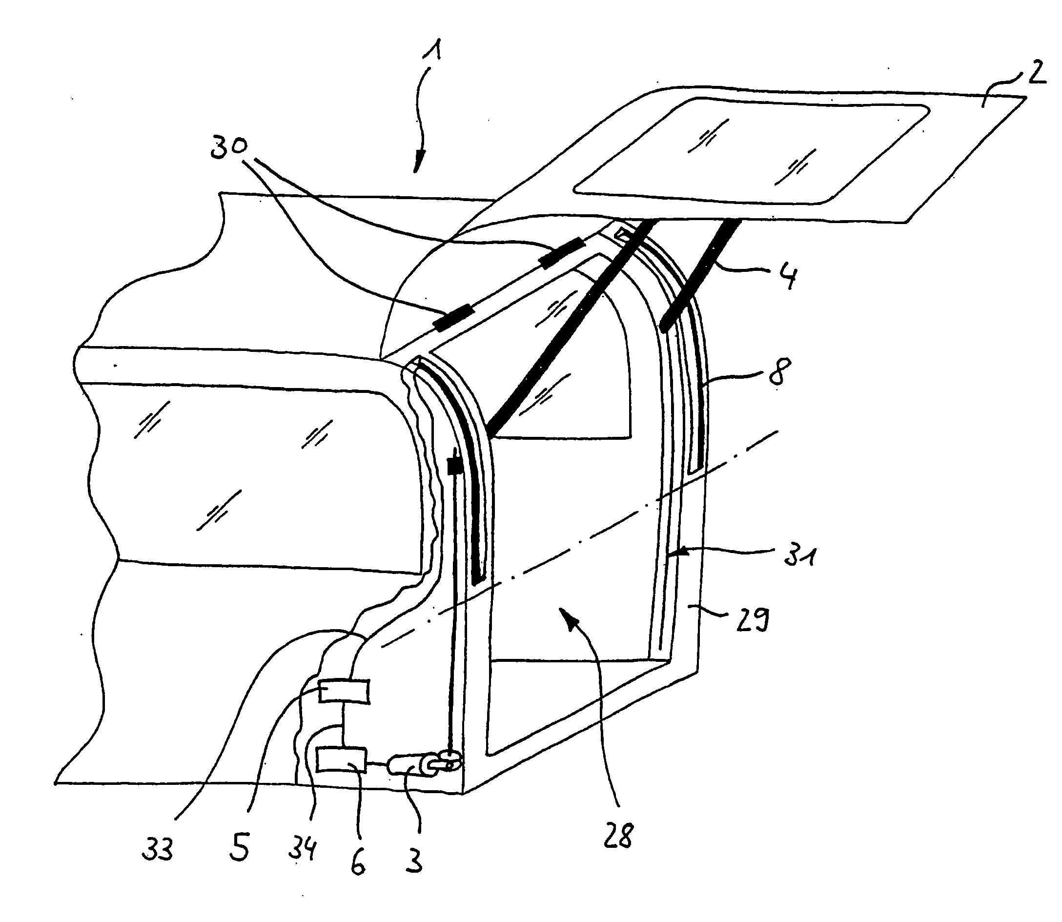
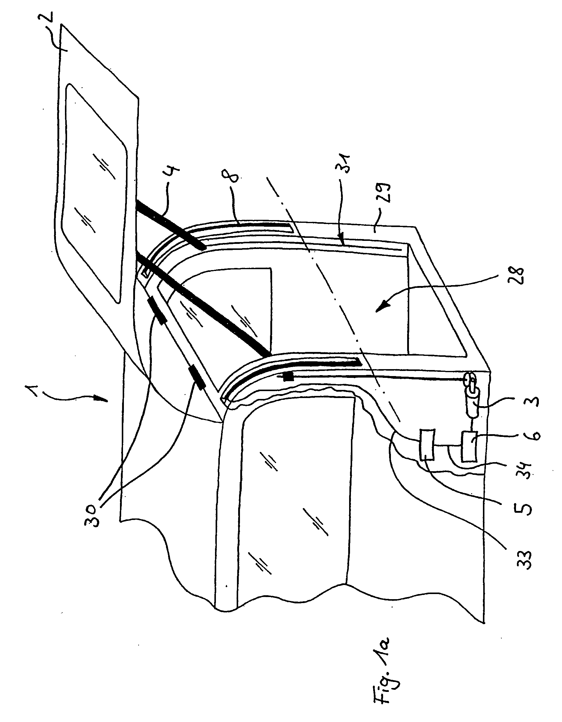
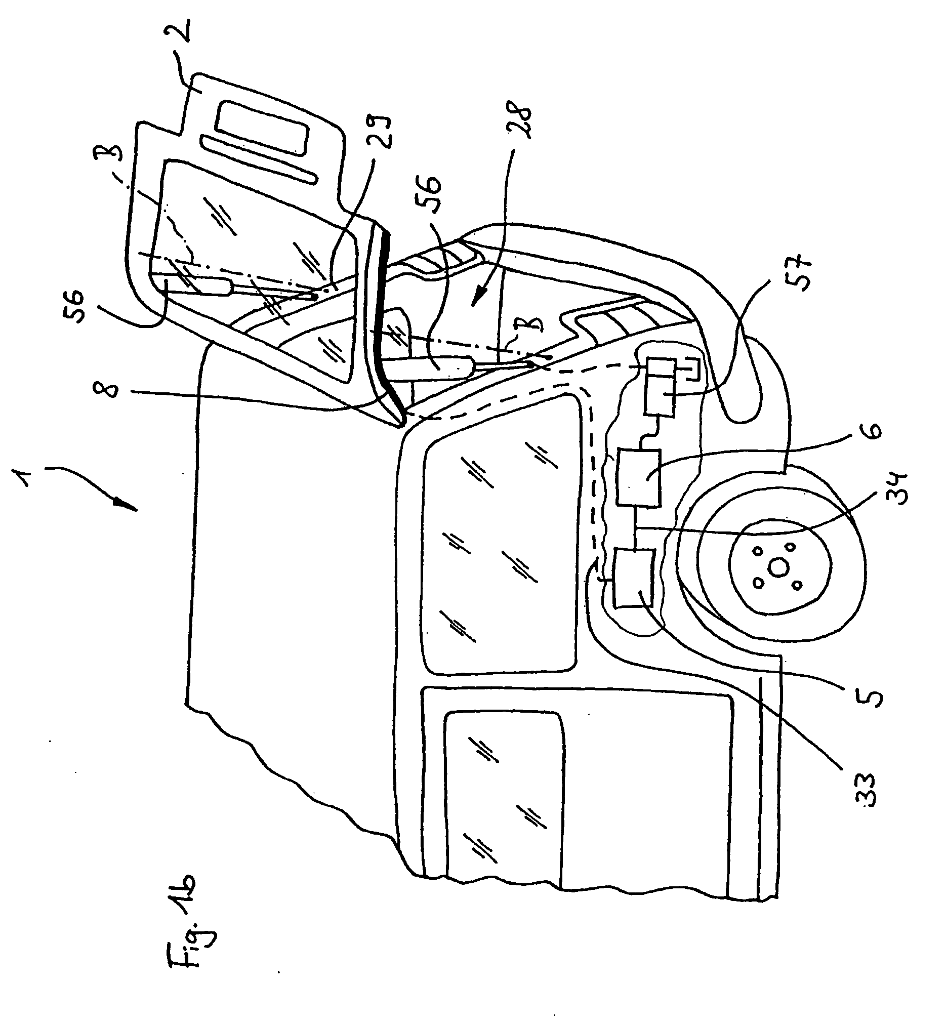
[0033] A motor vehicle tail area 1 shown in FIG. 1a has a rear luggage area opening 28, which is bounded by a tailgate frame 29. On a top side of the tailgate frame 29 a tailgate 2 is pivotably connected thereto via tailgate hinges 30. On either side of the insides of the luggage area opening 28 are provided guide rails 31 in each of which is slidably guided an operating rod 4 by means of a flexible screw spindle 32. The screw spindle 32 is rotated by a motor drive 3 and consequently permits a displacement of the operating rod 4, which is connected to the screw spindle 32 by means of a not shown clasp nut. Through the movement of the operating rods 4 along the guide rails 31 it is possible to exert an operating force on the tailgate 2 and this can be used for opening or closing the tailgate. The motor drive is controlled by a diagrammatically represented control unit 6. In order to implement a jamming protection for a lower region of the tailgate frame 29 use is made of the evaluati...


PUM


Abstract

Profile arrangement for jamming protection and injection mould are provided. A connecting portion of a support profile constructed as a plastic injection moulding and a fastening area of a zonally elastically flexible switching profile are constructed as positively interconnectable plug-in profilings.

Description

[0001] The present application claims the benefit of priority under 35 U.S.C. § 119 to German Patent Application No. 103 49 650.5, filed Oct. 20, 2003 and U.S. Provisional Patent Application No. 60 / 512,197, filed Oct. 20, 2003. The entire disclosure of the aforementioned applications is herein expressly incorporated by reference.BACKGROUND AND SUMMARY OF THE INVENTION [0002] The invention relates to a profile arrangement with a support profile, especially constructed as a plastic injection moulding, and with an at least zonally elastically flexible switching profile, which is connected by means of a fastening area to a corresponding connecting portion of the support profile, as well as an injection mould for the manufacture of the support profile. [0003] Such profile arrangements are known from the prior art for securing driven, automatically movable closure elements such as the tailgates of motor vehicles or safety doors in buildings or on machines. Profile arrangements are produce...

Claims


Application Information

Patent Timeline
IPC IPC(8): B60J5/10B60J10/00B60J10/08E05F15/00E05F15/12
CPCB60J5/101B60J10/00B60J10/0031B60J10/0062E05F2015/487E05Y2900/546H01H3/142E05F15/44E05F15/622B60J10/08B60J10/24B60J10/30B60J10/80
Inventor SCHERRAUS, MARC
Owner MAYSER
Why Eureka
Try Eureka