Disk array system and method of controlling disk array system
- Summary
- Abstract
- Description
- Claims
- Application Information
AI Technical Summary
Benefits of technology
Problems solved by technology
Method used
Image

Examples
Embodiment Construction
System Configuration
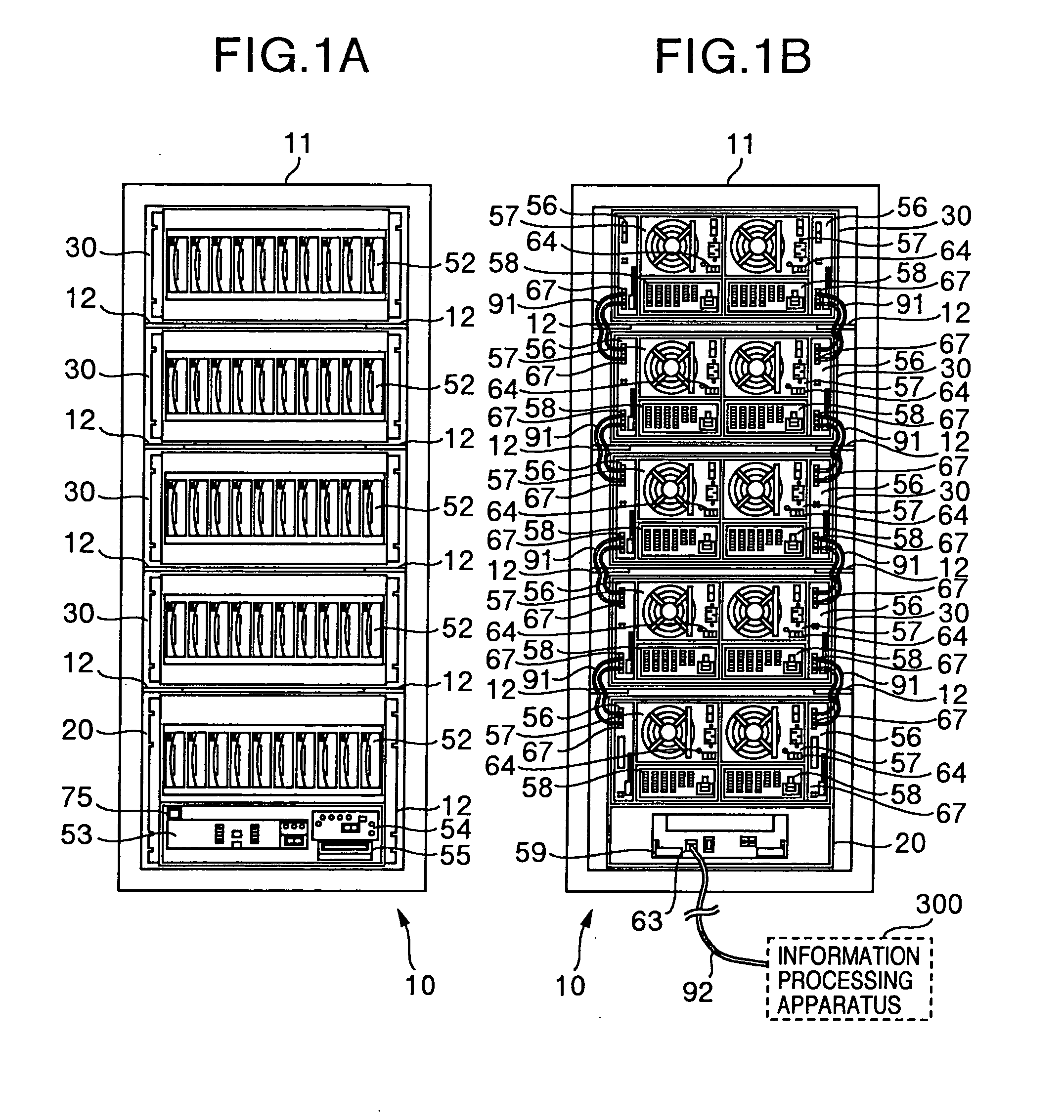
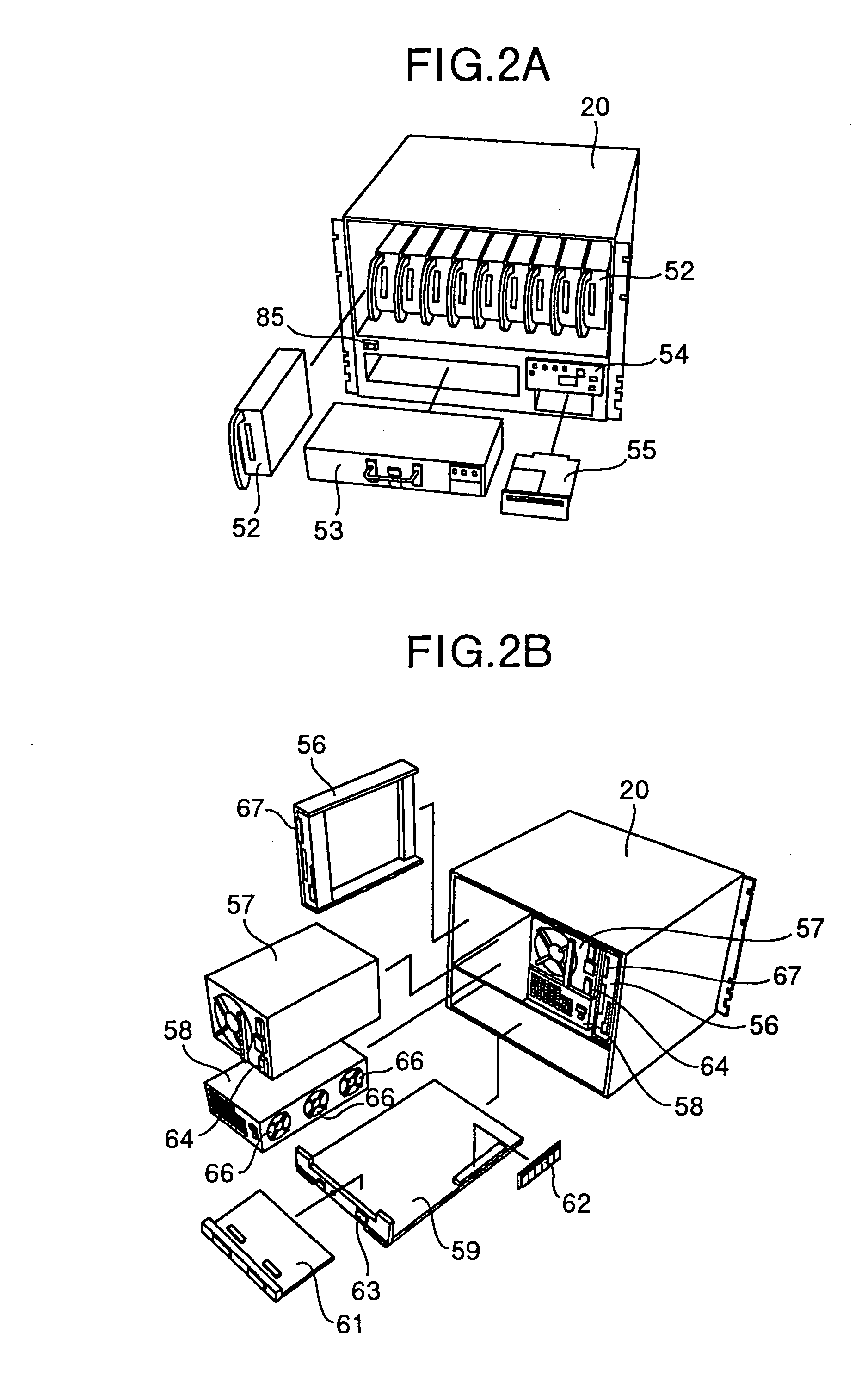
[0035]FIG. 1A is a front view of a disk array system 10 which will be described as an embodiment of the invention. FIG. 1B is a back view of the disk array system 10. FIG. 2A is a perspective view of a master housing 20 to be mounted on the disk array system 10, the master housing 20 being viewed from its front side. FIG. 2B is a perspective view of the master housing 20 viewed from its back side. FIG. 3A is a perspective view of an expansion housing 30 to be mounted on the disk array system 10, the expansion housing 30 being viewed from its front side. FIG. 3B is a perspective view of the expansion housing 30 viewed from its back side.
[0036] As shown in FIGS. 1A and 1B, the disk array system 10 is formed by using a rack frame 11 as a base. Mount frames 12 are formed in a plurality of stages disposed in the upper and lower on the inside left and right side surfaces of the rack frame 11, so as to extend in the front / rear direction. The master housing 20 and exp...
PUM
 Abstract
Description
Claims
Application Information
 - R&D
- Intellectual Property
- Life Sciences
- Materials
- Tech Scout
- Unparalleled Data Quality
- Higher Quality Content
- 60% Fewer Hallucinations
Browse by: Latest US Patents, China's latest patents, Technical Efficacy Thesaurus, Application Domain, Technology Topic, Popular Technical Reports.
© 2025 PatSnap. All rights reserved.Legal|Privacy policy|Modern Slavery Act Transparency Statement|Sitemap|About US| Contact US: help@patsnap.com