Optical module with accurate axial alignment using a platform

a technology of axial alignment and optical communication module, which is applied in the direction of optics, instruments, optical light guides, etc., can solve the problems of increasing manufacturing costs, large alignment errors, and high possibility of damage to the optical transceiving sub-assembly, so as to facilitate and improve the accuracy of connection guidance, prevent patterns, and minimize optical loss

Inactive Publication Date: 2005-06-02
OPTOELECTRONICS SOLUTIONS
View PDF2 Cites 3 Cited by
  • Summary
  • Abstract
  • Description
  • Claims
  • Application Information

AI Technical Summary

Benefits of technology

[0014] Accordingly, with the construction of the optical communication module of the invention, the optical communication module allows for easier and more accurate guidance of a connection between the optical transceiving sub-assemblies and the optical connector, which is the optical signal transmitting media, thereby minimizing the optical loss, and preventing the patterns on the printed circuit board from being damaged due to the insertion and disconnection of the optical connector.

Problems solved by technology

However, with such a conventional technology, there are not only large alignment errors between the optical communication module and the optical transceiving sub-assembly 104 due to a structural tolerance, but also a high possibility of damage of the optical transceiving sub-assembly 104 due to an excessive force caused by an excessive mechanical pressure applied to the optical transceiving sub-assembly 104 from the cover 200.
Furthermore, since a plurality of optical transceiving subassemblies 104 are directly mounted on the main body 500 of the optical communication module, the main body 500 has a shape significantly depending on outer features of the optical transceiving sub-assemblies 104, and thus requires different shapes according to the shapes of the optical transceiving sub-assemblies 104, thereby remarkably increasing manufacturing costs.
Moreover, since a force is applied to a mounting axis of the optical transceiving sub-assembly 104 when inserting or disconnecting an optical connector from the optical transceiving sub-assembly 104, damage occurs to patterns on a printed circuit board (PCB) connected to the lead of the optical transceiving sub-assembly 104, thereby disabling accurate transceiving of the optical signal.

Method used


Image

  • Optical module with accurate axial alignment using a platform
  • Optical module with accurate axial alignment using a platform
  • Optical module with accurate axial alignment using a platform

Examples


Embodiment Construction

[0022] Preferred embodiments will now be described in detail with reference to the accompanying drawings.

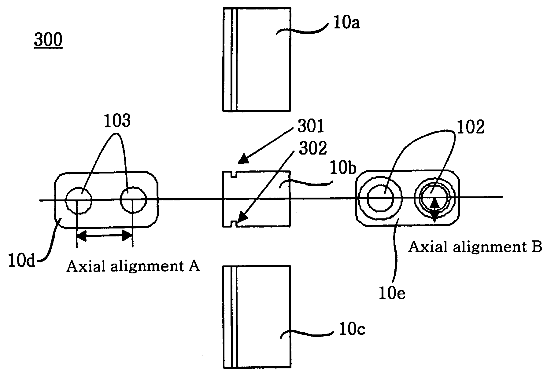
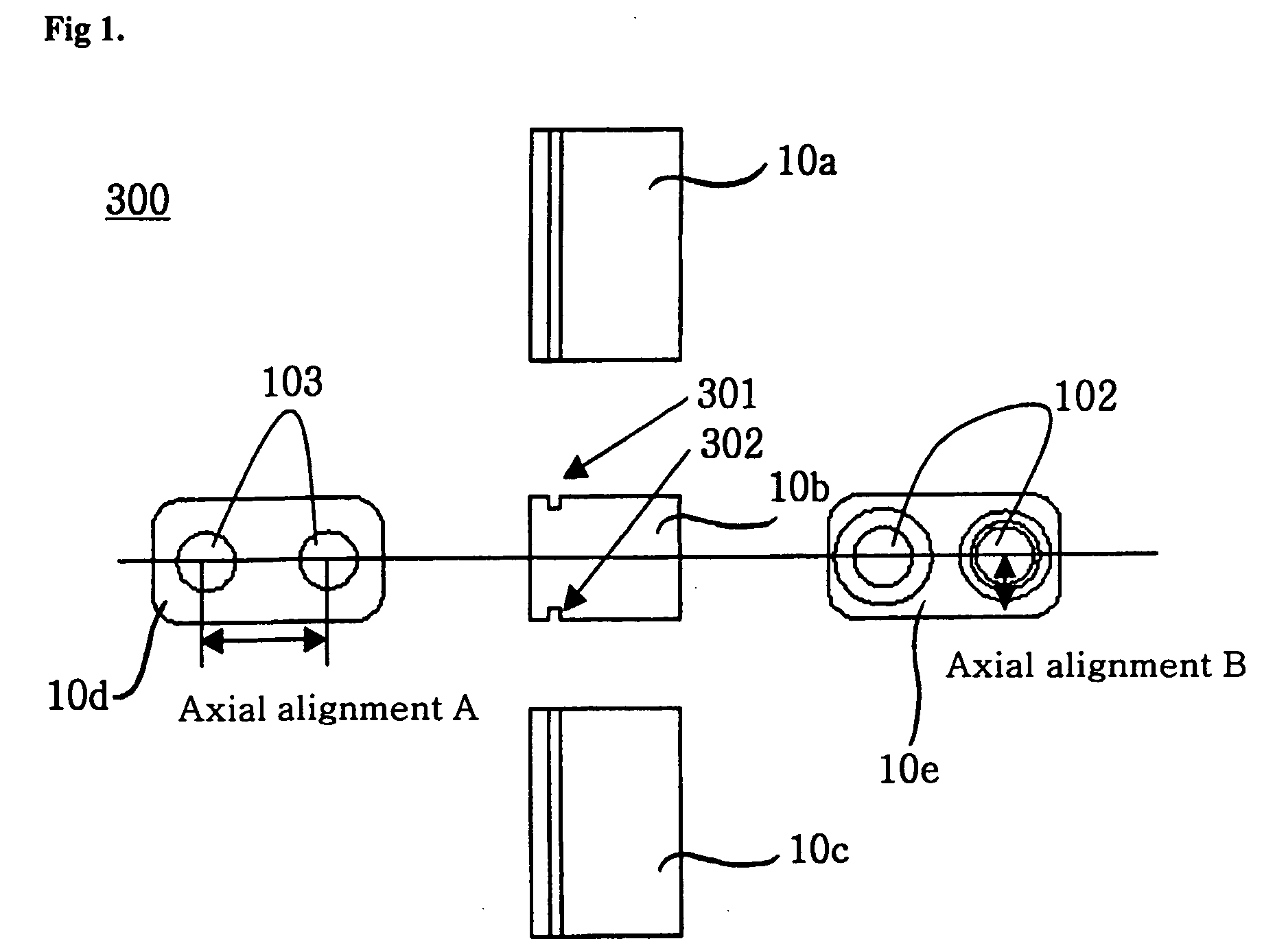
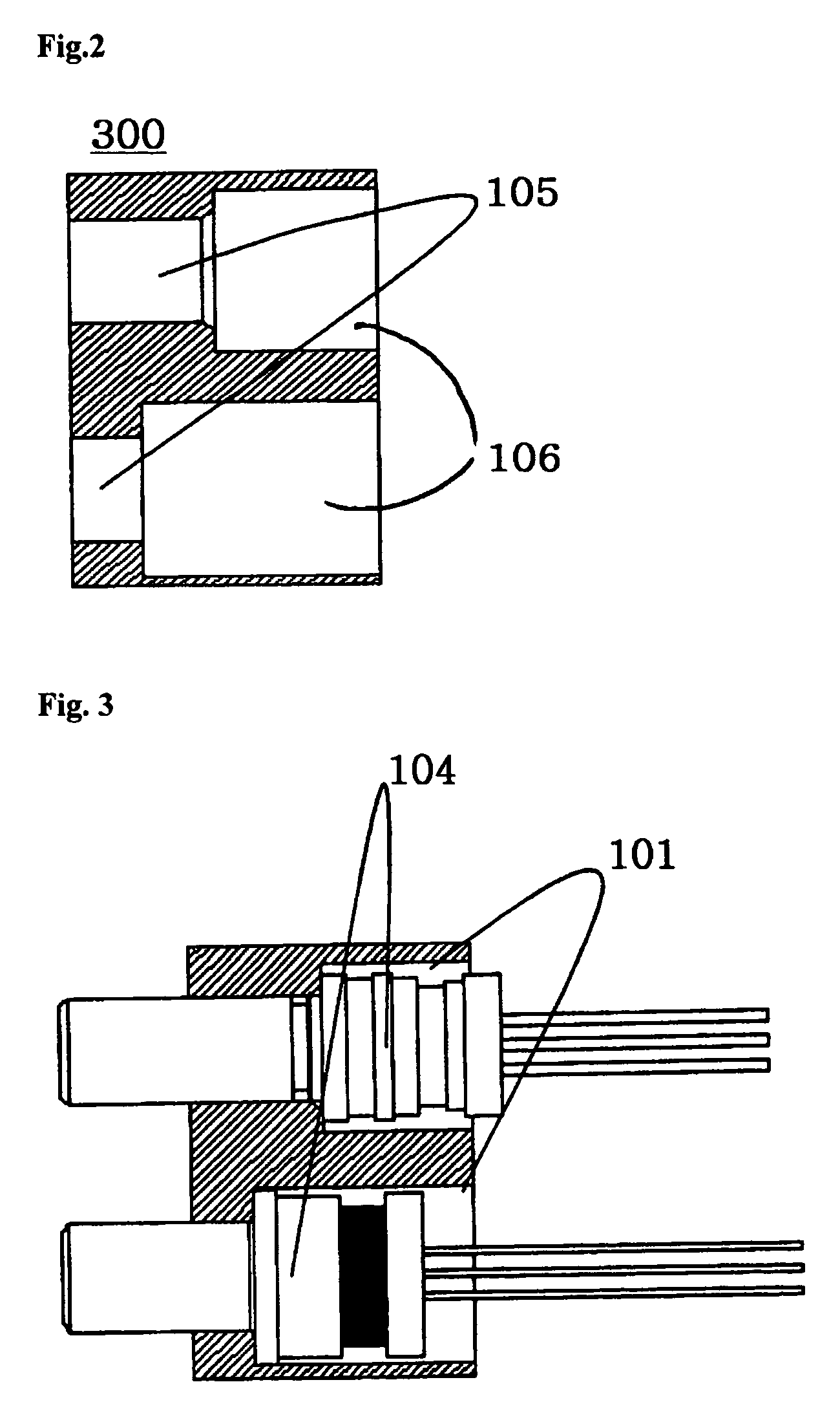
[0023]FIG. 1 is a partially enlarged view of the construction of a platform for axial alignment used for an optical communication module in accordance with one embodiment of the present invention, in which left, right, top, and bottom sides of the platform are shown. FIG. 2 is a cross-sectional view of the platform for axial alignment used for the optical communication module in accordance with one embodiment of the present invention. FIG. 3 is a cross-sectional view of a Transmitter Optical Sub-Assembly (TOSA) and a Receiver Optical Sub-Assembly (ROSA) assembled to the platform for axial alignment used for the optical communication module shown in FIG. 2. FIG. 4 is an exploded perspective view of the platform for axial alignment used for the optical communication module in accordance with one embodiment of the present invention. FIGS. 5a and 5b show a completed optical communic...


PUM


Abstract

An optical communication module is provided with a platform to provide an accurate axial alignment with optical transceiving subassemblies. In the optical communication module, axes of the optical transceiving sub-assemblies are aligned by virtue of previously established axial alignment of the platform, and the platform is fixed to a main body by inserting an insertion jaw of a cover into an insertion groove formed on an upper surface of the platform. After the optical transceiving subassemblies are inserted into the platform having the axial alignment required for a system, a bonding agent is filled into spaces defined in the platform, thereby preventing the axes from deviated by an external force. The optical communication module allows for easier and more accurate guidance of a connection between the optical transceiving sub-assemblies and the optical connector, thereby minimizing the optical loss, and preventing the patterns on the printed circuit board from being damaged due to the insertion and disconnection of the optical connector.

Description

BACKGROUND OF THE INVENTION [0001] 1. Field of the Invention [0002] The present invention relates to an optical communication module with a platform for axial alignment, and more particularly, to an optical communication module with a platform for axial alignment, designed to perform a reliable transmission of data to an optical transceiver, which transforms an optical signal to an electrical signal and vice versa, thereby mining data loss, and to allow for easier and more accurate axial alignment of an optical transceiving sub-assembly to an optical connector. [0003] 2. Description of the Related Art [0004] According to a conventional technology for mounting a Transmitter Optical Sub-Assembly (TOSA) and a Receiver Optical Sub-Assembly (ROSA) to an optical communication module, as shown in FIG. 6, after an optical transceiving sub-assembly 104 (TOSA / ROSA) is located on a mounting portion of a main body 500 of the optical communication module, a cover 200 is located thereon and fixed...

Claims


Application Information

Patent Timeline
Patent Type & Authority Applications(United States)
IPC IPC(8): G02B6/36G02B6/42
CPCG02B6/423G02B6/4246G02B6/4239G02B6/36
Inventor YANG, KWANG JINKIM, DAE JINKIM, DO IK
Owner OPTOELECTRONICS SOLUTIONS
Why Eureka
Try Eureka