Ocular implant and methods for making and using same

a technology of ocular implants and ocular arteries, which is applied in the field of ocular implants, can solve the problems of high intraocular pressure of glaucoma, drug delivery, and high labor intensity of surgeons, and achieve the effect of reducing the ingress of microorganisms

Inactive Publication Date: 2005-06-02
BECTON DICKINSON & CO
View PDF99 Cites 377 Cited by
  • Summary
  • Abstract
  • Description
  • Claims
  • Application Information

AI Technical Summary

Benefits of technology

[0013] It is yet another object of the present invention to provide a device and method that may be used as an implant having a size, shape and composition suitable for various applications, and including one or more filters, valves or restrictors to configure a desired response provided by the implant.
[0014] These and other objects are substantially achieved by providing an implant that is insertable through the clear cornea of the eye into the anterior chamber to drain aqueous humor, or similarly insertable through the sclera to introduce medications into the posterior chamber of the eye. The implant may include a substantially cylindrical body having one or more channels that permits drainage of aqueous humor from the anterior chamber to the external surface of the clear cornea, or permits substance release into the posterior chamber of the eye. The implant may further include a head that rests against an outer surface of the clear cornea or sclera, a foot that rests against an inner surface of the cornea or sclera, and one or more elongated filter members retainable within the channel of the body to regulate the flow rate of aqueous humor, introduce medications, and minimize the ingress of microorganisms.

Problems solved by technology

A major symptom of glaucoma is a high intraocular pressure, or “IOP”, which is caused by the trabecular meshwork failing to drain enough aqueous humor fluid from within the eye.
These procedures are very labor intensive for the surgeons and are often subject to failure due to scaring and cyst formations.
Another problem often related to the treatments described above includes drug delivery.
Currently there is no efficient and effective way to deliver drugs to the eye.
Drops are a very inefficient way of delivering drugs and much of the drug never reaches the inside of the eye.
Drugs may be injected into the eye, however, this is often traumatic and the eye typically needs to be injected on a regular basis.
PCT / US01 / 00350 above, however, existing shunts are also subject to numerous difficulties.
The first problem associated with shunt use is the regulation of aqueous outflow.
This problem typically results because the drainage rate of the fluid depends substantially on the mechanical characteristics of the implant until there has been sufficient wound healing to restrict fluid outflow biologically.
Effective balancing of biological and mechanical resistance to aqueous humor outflow remains a problem for implant-based drainage procedures.
Each of these mechanisms, however, may become a liability once wound healing has been established.
Restrictive elements within the implant, when combined with the restriction effected by wound healing, may inordinately reduce the rate of aqueous humor outflow possibly to non-therapeutic levels.
The second problem associated with existing shunt use is the possibility of intraocular infection.
Unfortunately, the presence of an implant provides a conduit through which bacteria can gain entry to the anterior chamber, thereby resulting in intraocular infections.
Certain drainage devices have introduced filters, valves or other conduit systems which serve to impede the transmission of infection into the anterior chamber, however, these mechanisms have limitations.
Even when effective in resisting the transit of microorganisms, they have hydraulic effects on fluid outflow that may also impair effective drainage.
Finally, a problem of local tissue tolerance arises with existing devices because the implant, as a foreign body, may incite tissue reactions culminating in local inflammation or extrusion.
This may be perceptible or uncomfortable for the patient, and these reactions to the presence of the implant may make its use clinically unsuitable.

Method used


Image

  • Ocular implant and methods for making and using same
  • Ocular implant and methods for making and using same
  • Ocular implant and methods for making and using same

Examples


Embodiment Construction

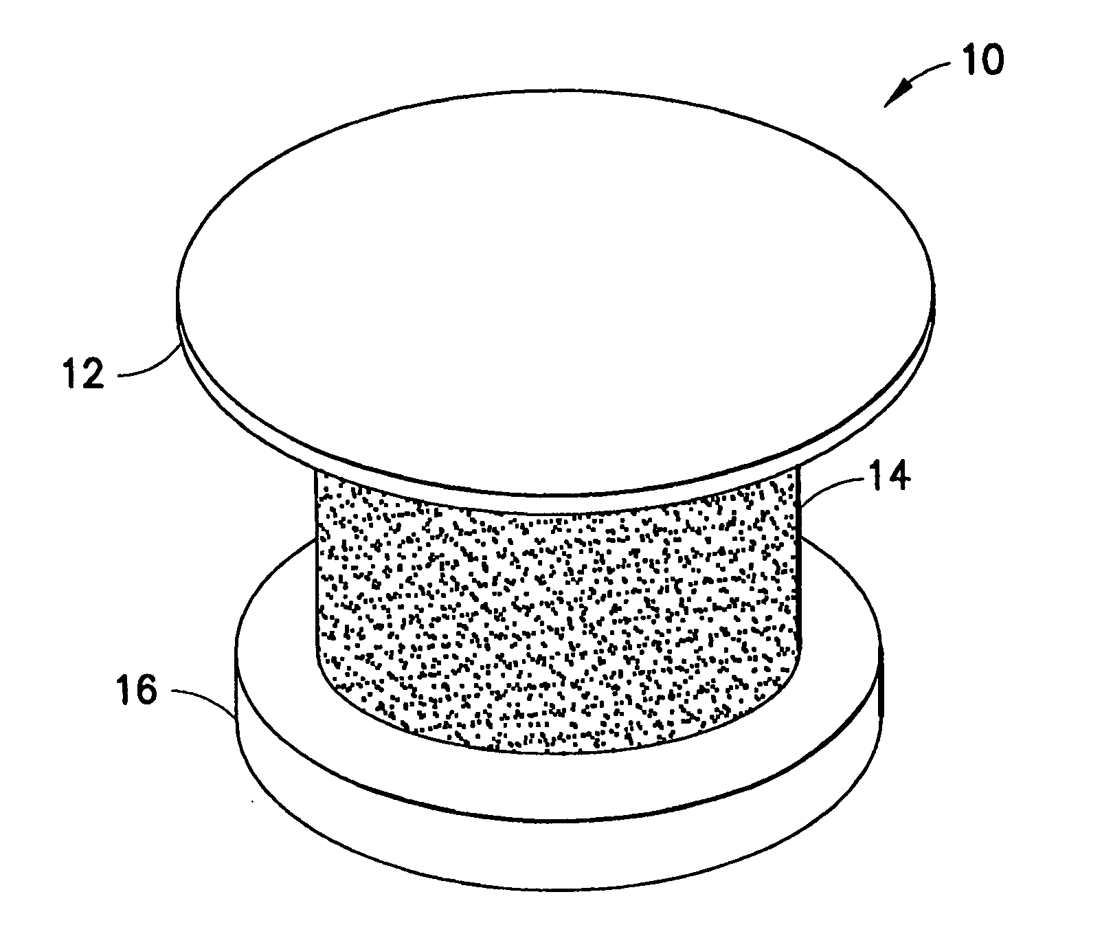
[0030] The transcornea shunt or implant (hereinafter “shunt”) has been developed to serve several purposes, such as to reduce the intraocular pressure (IOP) in the eye by shunting aqueous humor fluid from the anterior chamber of the eye, through the cornea, and to the terafilum. To do so, the shunt must be implanted through a small incision and into the cornea of the eye, actually extending between the inner and outer surface of the cornea. In yet another application, the shunt can be implanted through the sclera to introduce a substance into the posterior chamber of the eye.

[0031] As shown in FIG. 1, an enlarged perspective view of a shunt according to an embodiment of the present invention may be seen. In a representative embodiment, the shunt may be approximately one millimeter long with an outer diameter of approximately 0.5 mm. While the shunt illustrated in this figure is shown as a cylindrical structure, it is understood that other shapes of tubular conduits may be suitable ...


PUM


Abstract

An ocular implant device that is insertable into either the anterior or posterior chamber of the eye to drain aqueous humor and/or to introduce medications. The implant can include a substantially cylindrical body with a channel member that regulates the flow rate of aqueous humor from the anterior chamber or introduces medications into the posterior chamber, and simultaneously minimizes the ingress of microorganisms into the eye.

Description

CROSS-REFERENCE TO RELATED APPLICATIONS [0001] This application is a continuation-in-part of U.S. patent application Ser. No. 10 / 182,833, filed Dec. 27, 2002, which is the national stage of International Application No. PCT / US01 / 00350, filed Jan. 5, 2001, which claims the benefit of U.S. provisional patent application Ser. No. 60 / 175,658, filed Jan. 12, 2000, the entire content of each being incorporated herein by reference. International Application No. PCT / US01 / 00350 was published under PCT Article 21(2) in English.FIELD OF THE INVENTION [0002] The present invention relates to an ocular implant and more particularly, a filtered and / or flow restricting ocular implant for use through the cornea of an eye to relieve intraocular pressure, and for use through the sclera to introduce medications into the posterior chamber of the eye. In doing so, the embodiments of the present invention are applicable for both transcorneal and transscleral applications. BACKGROUND OF THE INVENTION [0003...

Claims


Application Information

Patent Timeline
Patent Type & Authority Applications(United States)
IPC IPC(8): A61F2/00A61F9/00A61F9/007A61M27/00
CPCA61F9/0017A61F9/00781A61F2250/0087A61F2250/0067A61M27/00A61F2210/0061
Inventor BENE, ERIC A.MORRILL, TIM J.MULHERN, MARGARET B.WANDEL, THADDEUS L.TAYLOR, JON B.MIR, LEON
Owner BECTON DICKINSON & CO
Why Eureka
Try Eureka