Process for copper free chrome plating of a vehicle wheel surface

a technology of chrome plating and vehicle wheels, which is applied in the field of vehicle wheels, can solve the problems of requiring abrasives and solvents, affecting the quality of chrome plating, and affecting the quality of chrome plating, and is known to produce a slightly distorted reflection in conventional polishing and buffing methods

Inactive Publication Date: 2005-06-09
HAYES LEMMERZ INT
View PDF28 Cites 21 Cited by
  • Summary
  • Abstract
  • Description
  • Claims
  • Application Information

AI Technical Summary

Benefits of technology

[0016] This invention relates to a method and improved cutting tool for machining a portion of a vehicle w

Problems solved by technology

However, such processes require abrasives and solvents.
When polishing and buffing is done by hand, the variations are more random due to fatigue of the human muscles and the inability to make exact dimensional repeated motions.
Thus, conventional polishing and buffing methods are known to produce a slightly distorted reflection that is similar to looking through an antique glass pane that has experienced some flow of its molecular structure.
Such flow can cause a

Method used


Image

  • Process for copper free chrome plating of a vehicle wheel surface
  • Process for copper free chrome plating of a vehicle wheel surface
  • Process for copper free chrome plating of a vehicle wheel surface

Examples


Embodiment Construction

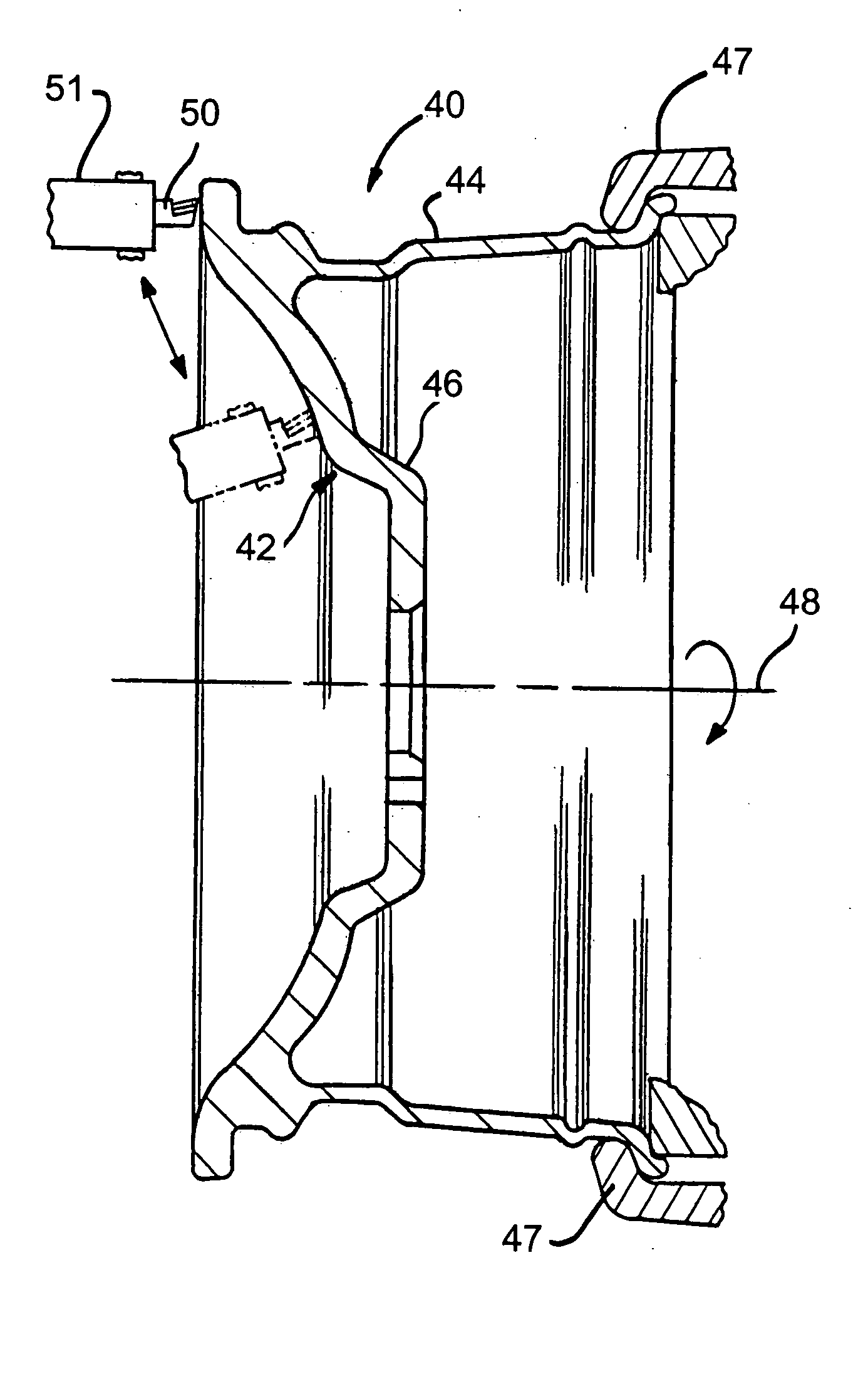
[0038] Referring again to the drawings, there is illustrated in FIG. 4, a sectional view of a one piece wheel 40 having an outboard surface, or wheel face, 42 and a process for finishing the wheel surface 42 in accordance with the present invention. The finishing involves cutting the wheel surface 42 with an improved cutting tool having a unique geometry that will be described below. An increased brightness or shine of the wheel surface is expected from the cutting process. Thus, the present invention is directed to smoothing the visible portions of a wheel face to cosmetically improve the appearance of the wheel face.

[0039] As shown in FIG. 4, the wheel 40 includes an annular wheel rim 44. A wheel disc 46 which includes the outboard surface 42 extends radially across the outboard end of the wheel rim 44. The invention contemplates clamping an inboard end of the wheel rim 44 in the jaws 47 of a lathe or a spinner chuck of a wheel lathe (not shown).

[0040] The wheel 40 is rotated ab...


PUM

PropertyMeasurementUnit
Angleaaaaaaaaaa
Pressureaaaaaaaaaa
Radiusaaaaaaaaaa

Abstract

A cutting tool having a hard tip is pressed with a uniform pressure against a surface of a vehicle wheel as the wheel is rotated to smooth and seal the surface. The smoothed and sealed wheel surface is then chrome plated with a process that includes applying a nickel layer directly upon smoothed and sealed wheel surface and a chromium layer over the nickel layer.

Description

CROSS REFERENCE TO RELATED APPLICATIONS [0001] This application is a Continuation-in Part of co-pending application U.S. patent application Ser. No. 10 / 756,856 filed Jan. 14, 2004 which claims the benefit of U.S. Provisional Patent Application No. 60 / 440,914 filed on Jan. 17, 2003, and of U.S. Provisional Patent Application No. 60 / 450,013 filed on Feb. 26, 2003 for the new matter contained therein, and which was a Continuation-in Part of U.S. patent application Ser. No. 10 / 309,726 filed Dec. 4, 2002, now U.S. Pat. No. 6,733,366 which issued on May 5, 2004 and which was, in turn, a divisional of U.S. patent application Ser. No. 09 / 725,528 filed on Nov. 29, 2000, now U.S. Pat. No. 6,540,450 which issued Apr. 1, 2003, and claimed the benefit of U.S. Provisional Patent Application No. 60 / 246,663 filed on Nov. 8, 2000.BACKGROUND OF INVENTION [0002] This invention relates in general to vehicle wheels and in particular to a method and cutting tool for machining a portion of the vehicle whe...

Claims


Application Information

Patent Timeline
IPC IPC(8): B23B5/02B23B27/14B60B3/02C25D5/02C25D5/44C25D7/00C25D11/38
CPCB23B5/02Y10T29/49496B23B2200/201B23B2200/28B23B2215/08B23B2222/04B23B2222/52B23B2222/88B23B2226/18B23B2226/31B23B2226/315B23B2270/26B23P15/00B60B3/02C23C28/023C25D5/02C25D5/022C25D5/14C25D5/42C25D5/44C25D7/00C25D11/38Y10T29/49885B23B27/145C25D5/627
Inventor GATTON, GEOFFREY L.GRENIER, LOUYEE, PETER
Owner HAYES LEMMERZ INT
Why Eureka
Try Eureka