Portable ultrasonic cleaner

Inactive Publication Date: 2005-06-09
MAH PAT Y
View PDF8 Cites 13 Cited by
  • Summary
  • Abstract
  • Description
  • Claims
  • Application Information

AI Technical Summary

Benefits of technology

[0009] The portable cleaning device of the present invention utilizes a forward housing which includes an ultrasonic radiator and an ultraviolet radiator. A rearwardly located detergent spray reservoir can be used to optionally apply what may preferably be a dilute solution of soap material. Once solvent is added to the soiled area, the ultrasonic front located area can be placed in contact with the wetted garment area and energized to bring the ultrasonic radiator into direct contact with the solution in contact with the soiled area. This enables less energy to be utilized due to the close

Problems solved by technology

Larger area cleaning is prohibited usually by the limited size of the devices provided, what is hoped to be a limited area of contamination, but more from the prohibitive cost and time associated from wide area cleaning.
Conventional devices which apply a liquid phase solvent for removal of the soiled material, even if successful, have the problem of removal of the solvent.
Light hydrocarbon solvents can be a health or fire hazard, but water tends to absorb into the garment and can take hours to naturally evaporate.
Another problems with conventional cleaning devices is the use of mechanical scrubbing.
Mechanical scrubbing can harm the fabric and cause picks and unraveling.
This is particularly true where the soiling is deep and where it is difficult to cause enough movement to enable the solvent to enter and adequately move the soiled mass with respect to the fabric.
Conventional cleaners are almost always mechanical, and none of the small cleaners are avail

Method used


Image

  • Portable ultrasonic cleaner
  • Portable ultrasonic cleaner
  • Portable ultrasonic cleaner

Examples


Example

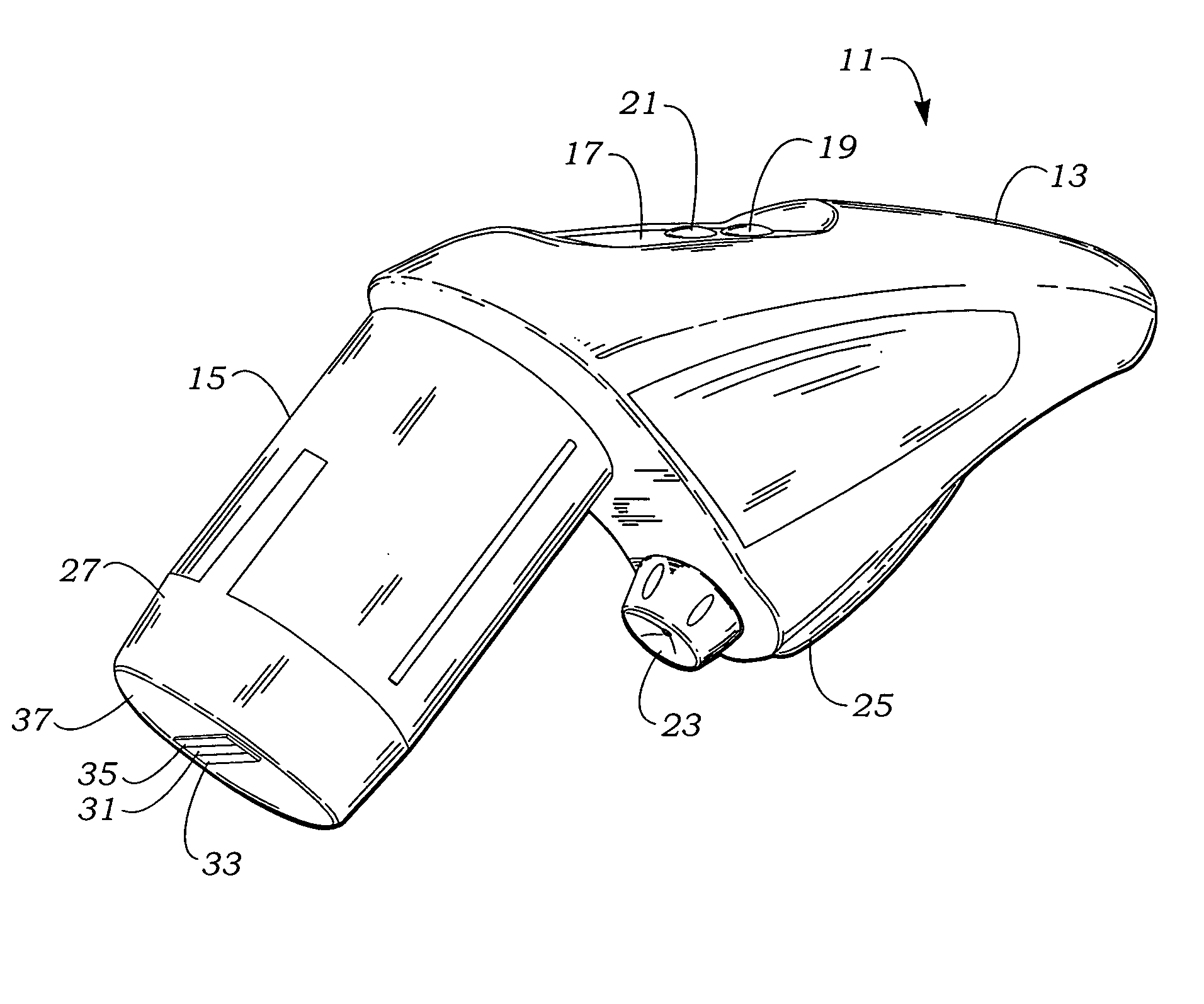
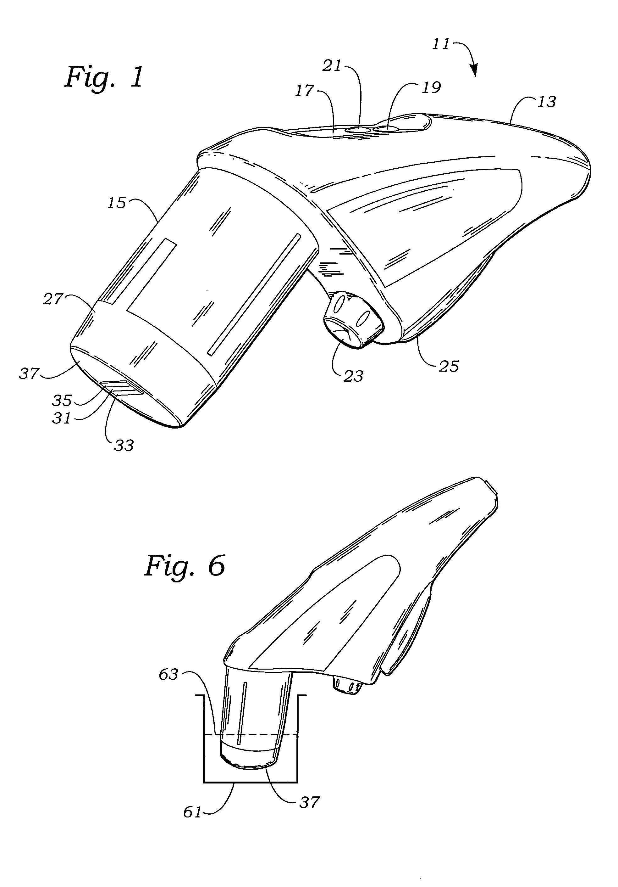
[0017] The description and operation of the invention will be best initiated with reference to FIG. 1 and which illustrates a portable ultrasonic cleaner 11 as an integrated unit having a rear housing section 13 and a front housing section 15. The rear housing section 13 is shaped for comfortable one-hand utilization, and includes a control panel 17 and may have an on / off switch 19 and power indicator 21.

[0018] The lower area of the rear housing section 13 may have an optional solvent / detergent spray nozzle 23 actuated by a pump handle 25. Other methods of delivery of fluid media may be utilized, and the overall area of the portable ultrasonic cleaner housing may be reduced with the optional elimination of the lower solvent / detergent reservoir and delivery mechanism.

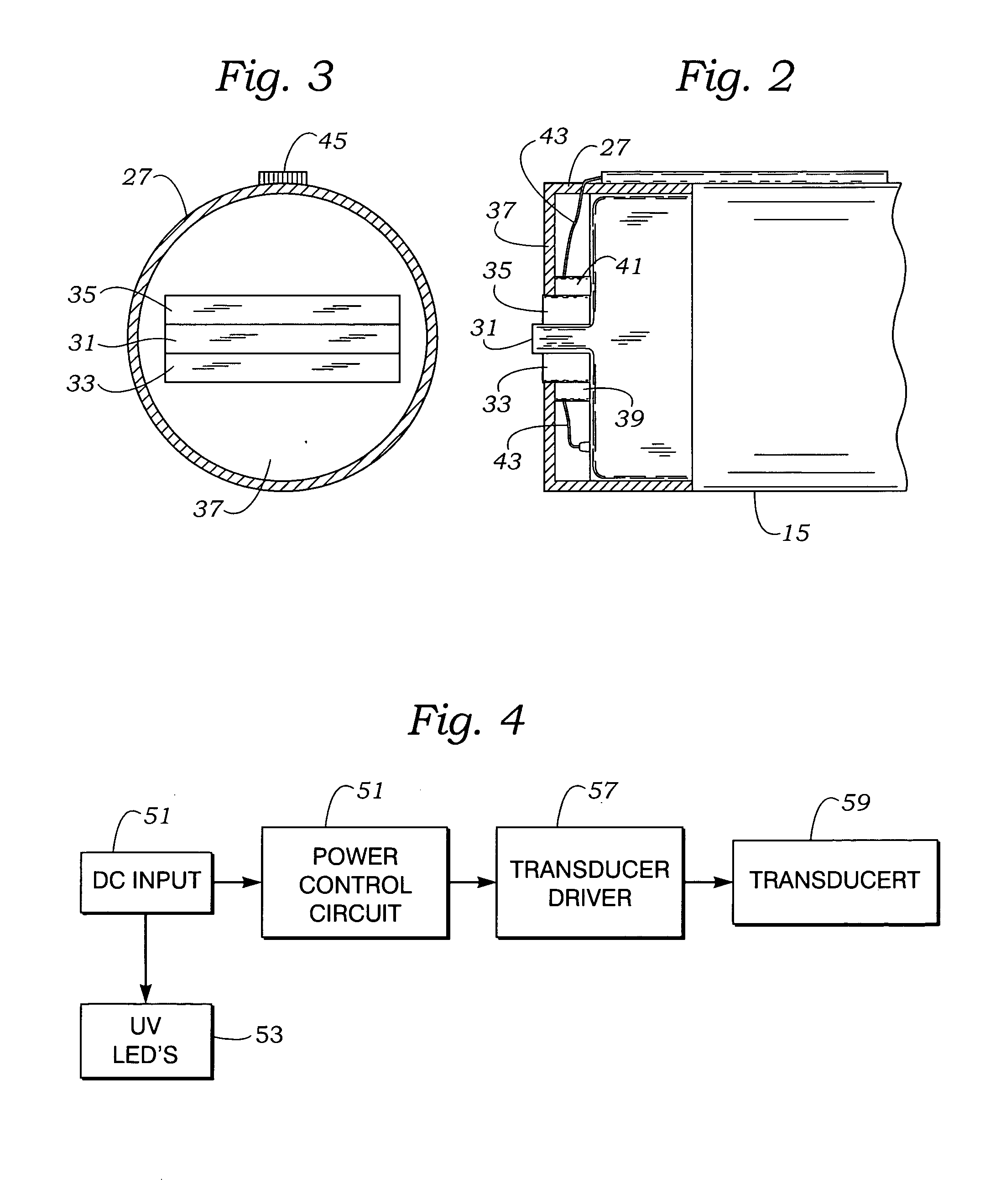
[0019] The front housing section 15 includes a detachable cap 27 to facilitate cleaning and service of the working face components should these components be contaminated by solvent, detergent, or other materials. At t...


PUM


Abstract

The portable cleaning device of the present invention utilizes a forward housing which includes an ultrasonic radiator and an ultraviolet radiator. A rearwardly located detergent spray reservoir can be used to optionally apply what may preferably be a dilute solution of soap material. Once solvent is added to the soiled area, the ultrasonic front located area can be placed in contact with the wetted garment area and energized to bring the ultrasonic radiator into direct contact with the solution in contact with the soiled area. This enables less energy to be utilized due to the close proximity to a limited liquid volume in the immediate area of the fabric and closely co-located with the soiled mass. Actuation of a ultraviolet radiator is activated simultaneously with the actuation of the ultrasonic radiator to begin to help with the odor problem from the outset of the cleaning activity. The combination of ultrasonic and ultraviolet energy input also provides energy to the solvent within the fabric to both increase the efficiency of cleaning and to assist the evaporation of solvent. The portable cleaning device can also be utilized with other solvents supplied by the user.

Description

FIELD OF THE INVENTION [0001] The present invention relates to improvements in convenience devices designed to perform garment cleaning over concentrated areas, and more specifically to a portable device utilizing ultrasonic cleaning and ultraviolet radiation. BACKGROUND OF THE INVENTION [0002] Portable cleaning devices are known which attempt to physically isolate areas of garment material to perform emergency cleaning or removal of contaminants over a limited area of the garment material. Larger area cleaning is prohibited usually by the limited size of the devices provided, what is hoped to be a limited area of contamination, but more from the prohibitive cost and time associated from wide area cleaning. [0003] Portable cleaning devices are valued for not only their area specificity but for the ability to complete the cleaning process in a short time and to return the soiled garment area to a pre-soiled state and eliminate any indication of the cleaning process. Conventional devi...

Claims


Application Information

Patent Timeline
IPC IPC(8): A47L13/10A47L13/26A47L25/08B08B3/12B08B7/00C11D11/00D06F3/00
CPCA47L13/10A47L13/26C11D11/007B08B3/12B08B7/0057A47L25/08
Inventor MAH, PAT Y.
Owner MAH PAT Y
Why Eureka
Try Eureka