Method of detecting a water leak in a locomotive

a technology of locomotives and water leaks, applied in the direction of measuring devices, structural/machine measurement, instruments, etc., can solve the problems of a variety of locations where water leaks have been known in a locomotive, and the repair of engine components, particularly engine power assemblies, is a costly and time-consuming matter

Active Publication Date: 2005-06-09
GE GLOBAL SOURCING LLC
View PDF9 Cites 8 Cited by
  • Summary
  • Abstract
  • Description
  • Claims
  • Application Information

AI Technical Summary

Problems solved by technology

Water leaks have been known to occur at a variety of locations in a locomotive, both from engine components and from cooling system components apart from the engine, i.e. piping, valves, pumps, sight glass, etc.
While it may be relatively easy to repair or replace some cooling system components, the repair of engine components, particularly engine power assemblies, is a costly and time-consuming matter.

Method used


Image

  • Method of detecting a water leak in a locomotive
  • Method of detecting a water leak in a locomotive
  • Method of detecting a water leak in a locomotive

Examples


Embodiment Construction

[0008] The present inventors have found that a high percentage of the power assemblies that are removed from locomotive engines for water leak repairs based on the commonly accepted “squeeze test” were not in fact actually leaking once they are disassembled and fully inspected. The inventors believe that such power assemblies are removed in error because the prior art water leak detection process is not capable of accurately determining the source of a water leak detected during a squeeze test. In particular, the inventors have found that water leaking from within a locomotive engine may migrate within the engine to reveal itself at a location remote from the actual source of the leak. Such transient water may then be misinterpreted as an indication that a watertight component is leaking.

[0009] In addition, the “squeeze test” is done under static conditions (i.e., with no flow of water through the engine) and typically at cold (as opposed to normal operating) temperature engine con...


PUM


Abstract

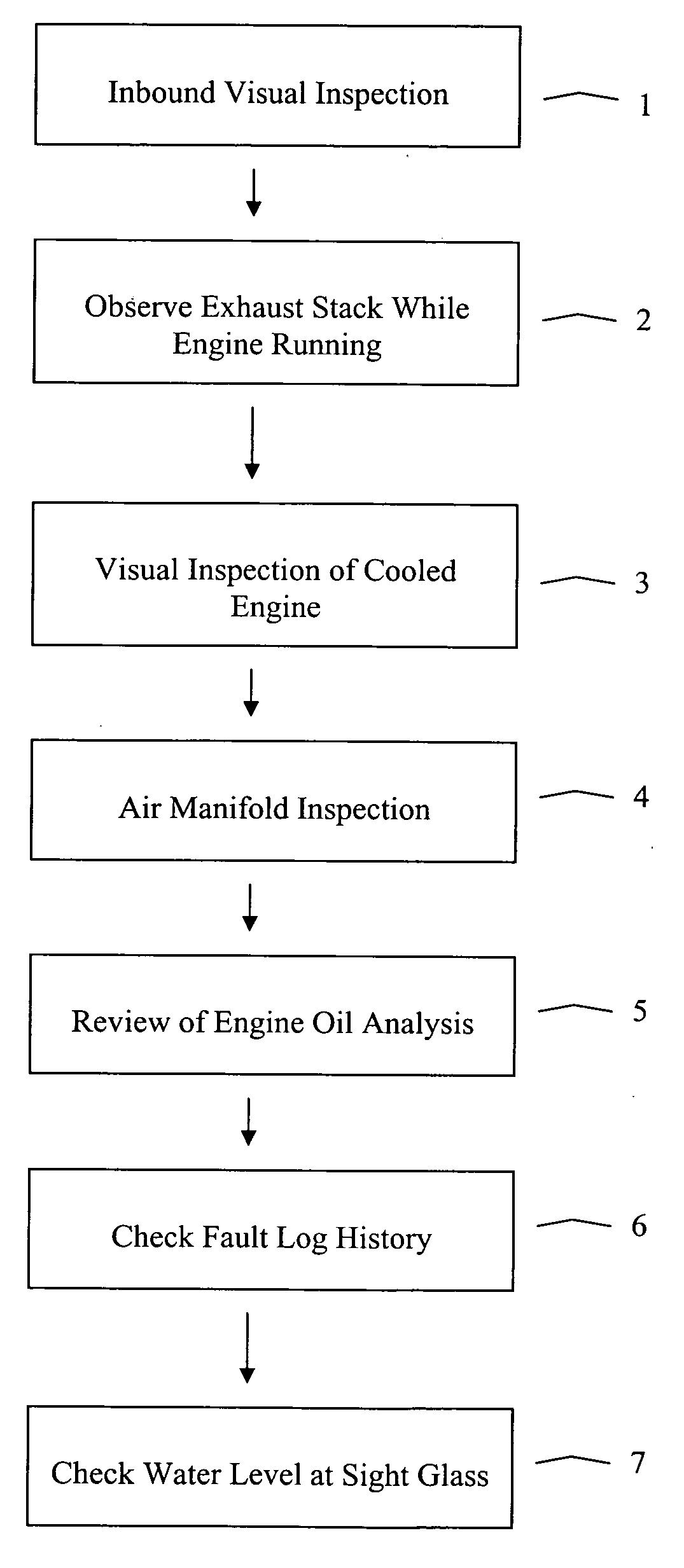
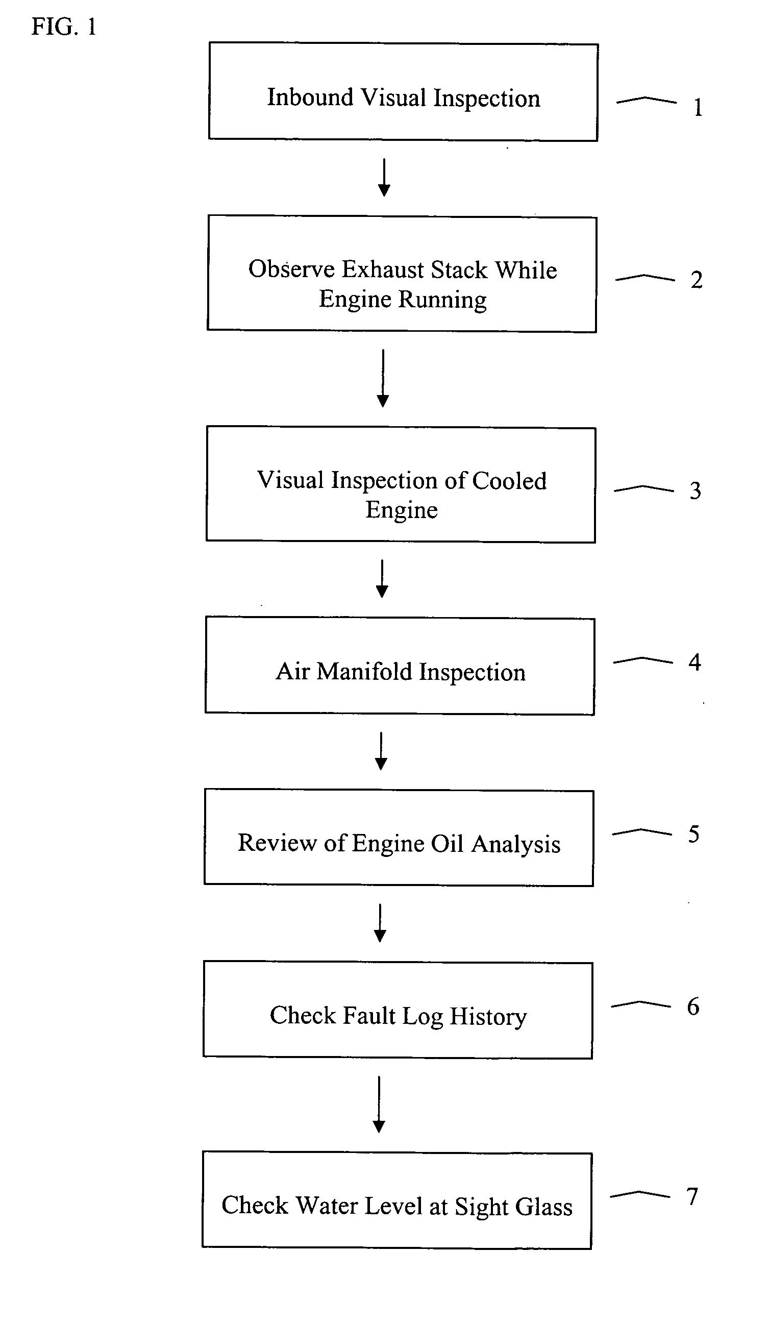
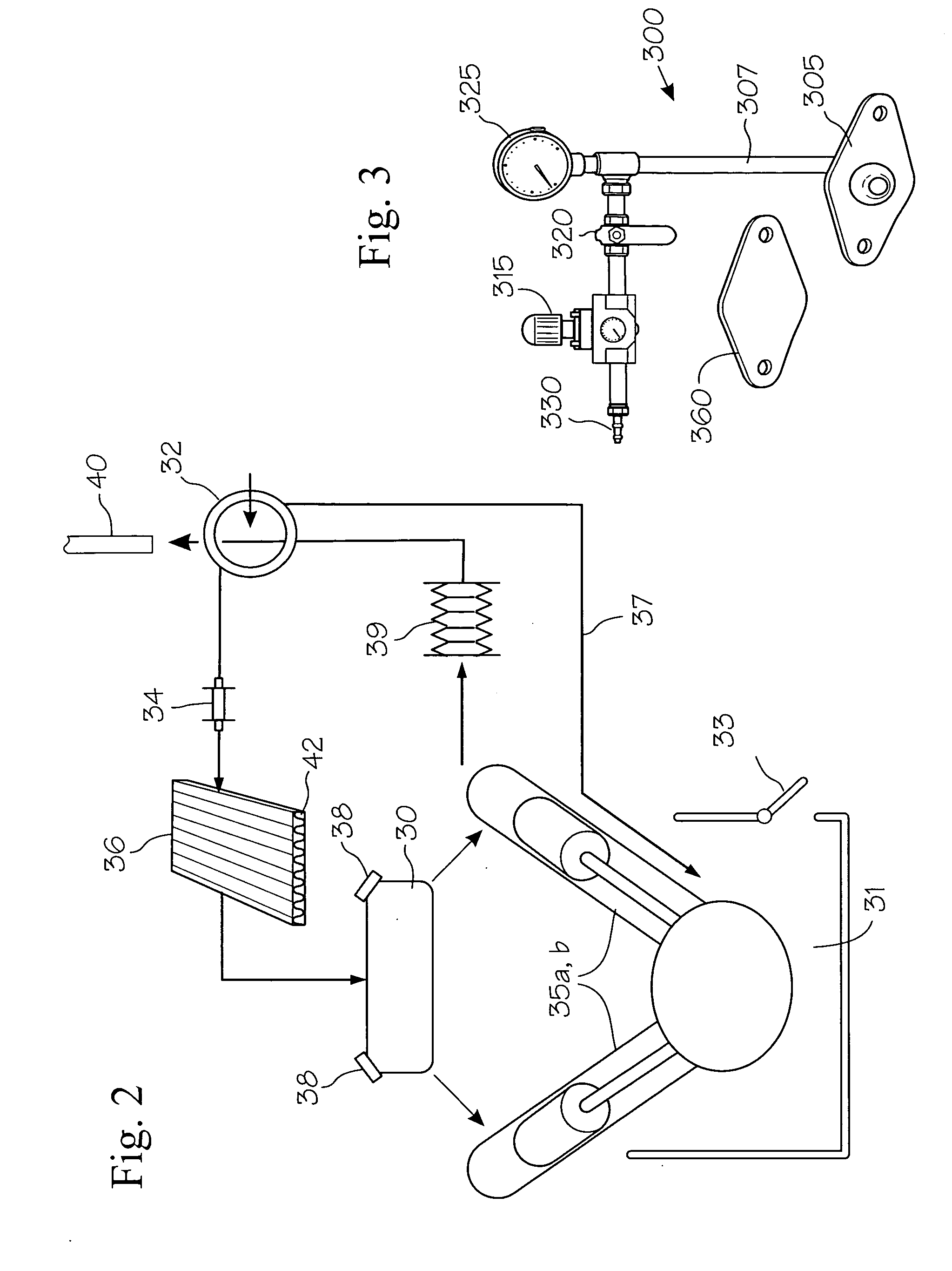
Disclosed herein are methods for detecting a water leak in a locomotive engine cooling system comprising numerous components, each being a potential source of leakage of water. The method typically comprises performing at least one inspection providing an indication of a water leak from an engine cooling system of the locomotive. The step of performing at least one inspection may comprise at least one of several steps including performing a visual inspection to determine if water is leaking from a portion of the cooling system external to the engine; performing a visual inspection of exhaust of the engine to detect an indication of water vapor in the exhaust; performing a visual inspection to detect an indication of water leaking into an intake air manifold 30 of the engine; performing an engine oil analysis to detect water in the engine lubricant; reviewing a fault log history for the locomotive; and checking a level of a cooling system sight glass. The method allows for the isolation of potential sources of the water leak from one another so as to prevent false positive leak identification caused by transient water flow between the potential sources. If an engine cylinder assembly is a component identified as a potential source of the water leak during the water pressurization test, the method enables further testing to confirm leakage at such cylinder assembly, before undertaking the costly and time-consuming process of removing the cylinder assembly from the engine. Cylinder assemblies can be tested for leaks by performing an air leak test disclosed herein.

Description

[0001] This application claims the benefit of U.S. Provisional Application No. 60 / 527,724, filed Dec. 8, 2003, incorporated herein by reference.FIELD OF THE INVENTION [0002] This invention relates generally to the field of maintenance and repair, and more particularly to a method of detecting a water leak in a locomotive. BACKGROUND OF THE INVENTION [0003] Locomotives are returned periodically to a service facility for preventative and corrective maintenance. The engine cooling system of a locomotive is an important system that is routinely inspected. The frequency of inspection of a locomotive cooling system may vary from one railroad to another, with annual and condition-based inspections often specified. The inspection is performed by visually checking for leaks while applying hydrostatic pressure to the cooling system with the locomotive engine in a cold shutdown condition; commonly called a “squeeze test.” If a fluid leak is detected, the suspect part is repaired or it is remov...

Claims


Application Information

Patent Timeline
Patent Type & Authority Applications(United States)
IPC IPC(8): G01M3/04
CPCG01M3/04
Inventor CRYER, ROBERT DOUGLASSONNEY, THOMAS CHARLEKUMAR, MANOJ P.RUPRECHT, WILLIAM JOSEPH IIIWAUGAMAN, CHARLES JOSEPHSWEDBERG, MATTHEW LEEMCANDREW, DENNIS WILLIAMMAYLE, JOHN ALBERT
Owner GE GLOBAL SOURCING LLC
Why Eureka
Try Eureka