
Method for cleaning substrate and apparatus therefor

a substrate and cleaning technology, applied in the direction of cleaning processes and apparatus, cleaning using liquids, chemical instruments and processes, etc., can solve the problems of affecting the efficiency of cleaning operations, so as to achieve the effect of reducing the number of wirings, and avoiding deterioration of cleaning techniques

Inactive Publication Date: 2005-06-09
KAIJOO KK
View PDF18 Cites 18 Cited by
  • Summary
  • Abstract
  • Description
  • Claims
  • Application Information

AI Technical Summary

Benefits of technology

[0011] It is an object of the present invention to provide a method for cleaning a substrate and an apparatus therefor which are capable of increasing a particle removal ratio at which particles firmly adhering to an object to be cleaned are removed therefrom and increasing a throughput.
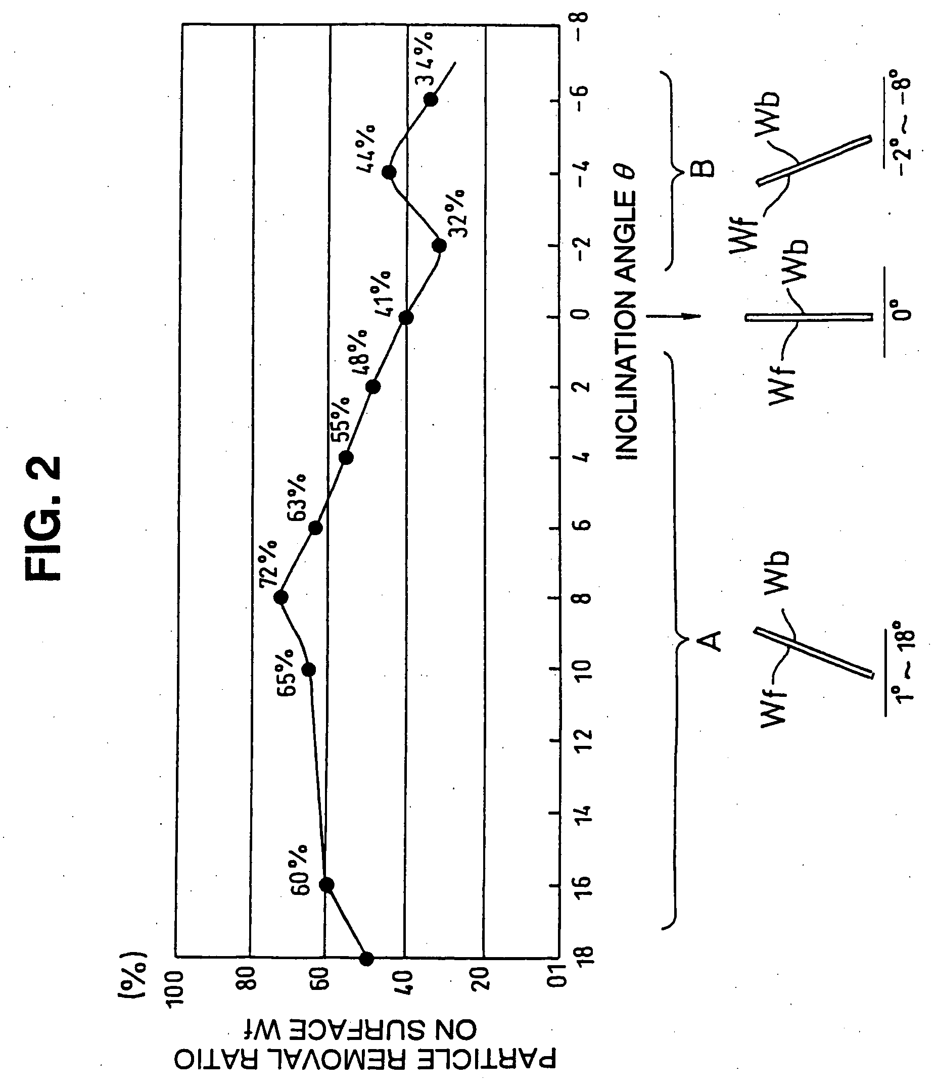
[0015] In a preferred embodiment of the present invention, the inclination angle θ is set to be within a range of between more than 0° and equal to or less than 16° (0°<θ≦16°). A change of the inclination angle θ from “positive” to “negative” causes ultrasonic vibration energy to be applied directly to the front surface of the substrate, to thereby deteriorate a particle removal ratio at which particles adhering to the front surface are removed therefrom. The inclination angle of 0° means that the substrate is vertically arranged in the cleaning tank. A change of the inclination angle from “negative” to “positive” permits ultrasonic vibration energy to be applied to the rear surface of the substrate, to thereby increase a particle removal ratio at which particles adhering to the front surface of the substrate are removed therefrom. The inclination angle θ above 16° leads to a deterioration or reduction in particle removal ratio or fails to increase it. The inclination angle is preferably set to be within a range between more than 0° and equal to or less than 10° (0°<θ≦10°).
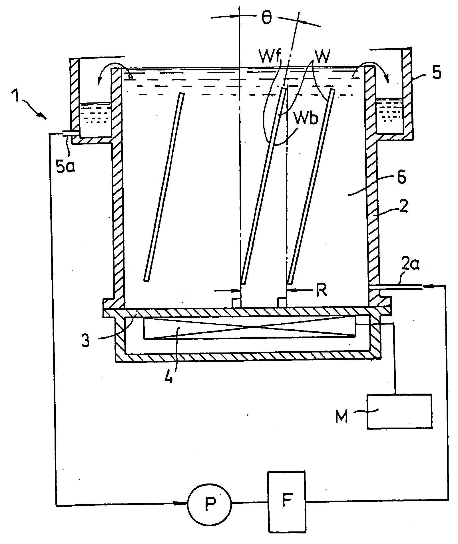
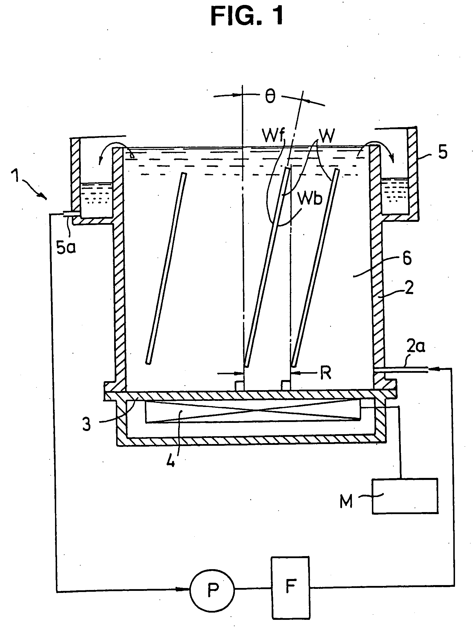
[0018] In the substrate cleaning apparatus of the present invention, as described above, the bottom of the cleaning tank is arranged in an inclined manner. Such arrangement of the bottom, when the substrate is placed in the cleaning tank so as to extend in a vertical direction, permits ultrasonic vibration energy to be applied at a predetermined inclination angle to the substrate, resulting in particles which adhered to the substrate being efficiently removed therefrom. The inclination angle θ within a range of 0°<θ≦16° indicates an angle between the substrate vertically placed in the cleaning tank and a direction of acoustic streaming in the cleaning liquid from a plane of the inclined bottom of the cleaning tank. Also, the substrate is vertically placed in the cleaning tank as described above. This permits the substrate to be located at a predetermined position without requiring any cassette for carrying the substrate thereon, so that the cleaning operation may be increased in efficiency. Of course, the substrate may be arranged in a cassette-load mode. Also, the substrate is vertically placed in the cleaning tank, therefore, the cleaning is preferably carried out while rotating the substrate. Further, the bottom of the cleaning tank is provided thereon with the vibration plate by way of example. Alternatively, the present invention may be constructed so that the bottom plate of the cleaning tank functions as the vibration plate as well.
[0019] In a preferred embodiment of the present invention, the bottom of the cleaning tank is constituted by two members inclinedly arranged. Such construction permits both surfaces of the substrate to be efficiently cleaned in a single cleaning tank. For example, when the bottom of the cleaning tank is inclined in only one direction, only one surface of the substrate is predominantly cleaned. Thus, efficient cleaning of both of the front and rear surfaces of the substrate requires two cleaning tanks, each for cleaning a respective one of these surfaces. On the contrary, in the embodiment, the bottom of the cleaning tank is constituted by the two members which are inclined in two directions different from each other. Such arrangement permits acoustic streaming in the cleaning liquid generated due to an ultrasonic vibration to progress in different directions, so that vibration energy may be efficiently applied to both surfaces of the substrate. This results in cleaning of both surfaces of the substrate being attained in a single cleaning tank. For example, the substrate cleaning method using the thus-constructed cleaning tank may be practiced in a manner to alternately vibrate vibration plates mounted on the members of the bottom of the cleaning tank inclined at different angles, so that the front and rear surfaces of the substrate may be alternately cleaned.
[0020] Moreover, in the present invention, a first cleaning tank in which the vibration plate is provided so as to permit acoustic streaming in the cleaning liquid to proceed toward a center of the cleaning tank and a second cleaning tank in which it is arranged so as to permit acoustic streaming in the cleaning liquid to proceed toward a side wall of the cleaning tank may be arranged in juxtaposition. In such arrangement, a number of substrates or wafers are concurrently placed in the first cleaning tank and then vertically placed in the second cleaning tank. This results in both surfaces of the wafers being effectively cleaned. Cleaning of the substrates in the cleaning tanks having the bottoms inclined at different angles, respectively, leads to an increase in throughput.

Problems solved by technology

Wiring arrangement in the semiconductor device has been complicated with an increase in the number of wirings laminated, during which techniques of rendering asperities on a surface of the substrate flat have been widely used.
Recent progress in manufacturing of a semiconductor device causes conventional flattening techniques such as etch back, reflow or the like to fail to accommodate to the manufacturing.
Thus, brush cleaning and scrub cleaning are effective to remove the particles from the wafer, however, such cleaning techniques are deteriorated in throughput.
However, such an ultrasonic cleaning apparatus causes the semiconductor substrates to be vertically placed in the cleaning tank.
Thus, it has a disadvantage of failing to increase a particle removal ratio at which particles firmly adhering to the substrate after the CMP processing are removed from the substrate.
Unfortunately, this may often lead to damage to a surface of the wafer, although it permits an increase in particle removal ratio.
However, the cleaning techniques as well are deteriorated in throughput.
This renders the cleaning tank significantly large-sized.
Also, the cleaning techniques cause an ultrasonic vibration generated by the ultrasonic transducer 4 to be applied to a wall of the cleaning tank opposite to the ultrasonic transducer 4, resulting in the wall of the cleaning tank being highly damaged.

Method used


Image

  • Method for cleaning substrate and apparatus therefor
  • Method for cleaning substrate and apparatus therefor
  • Method for cleaning substrate and apparatus therefor

Examples


first embodiment

[0034] Now, an embodiment of a substrate cleaning method according to the present invention will be described with reference to FIGS. 1 to 3C. First of all, a substrate cleaning apparatus used for practicing a substrate cleaning method of the illustrated embodiment will be described with reference to FIG. 1, which is a schematic sectional view of the apparatus. The substrate cleaning apparatus shown in FIG. 1 includes a cleaning tank 1 including a tank body 2. The tank body 2 of the cleaning tank 1 has a vibration plate 3 arranged at a bottom thereof. The vibration plate 3 is provided on a rear surface thereof with an ultrasonic transducer 4. The cleaning tank 2 is provided on an upper portion thereof with an overflow receiver 5. The tank body 2 is provided at a lower portion thereof with a cleaning liquid feed port 2a. The overflow receiver 5 is provided at a lower portion thereof with a cleaning liquid discharge port 5a. The cleaning tank 1 is filled therein with a cleaning liquid...

second embodiment

[0048] Referring now to FIGS. 4 to 6D, a second embodiment of a substrate cleaning method and an apparatus therefor according to the present invention will be described hereinafter. In the first embodiment described above, the substrate cleaning is carried out in such a manner that the inclination angle θ of the wafers with respect to the vertical plane of the vibration plate is provided, to thereby improve a particle removal ratio at which particles adhering to the surfaces of the wafers which face upward are removed therefrom. A cleaning apparatus of FIG. 4 is constructed so as to have substantially the same advantage as that of the above-described first embodiment by inclining a vibration plate 13.

[0049] The substrate cleaning apparatus of the second embodiment shown in FIG. 4 includes a cleaning tank 11 including a tank body 12. The tank body 12 of the cleaning tank 11 has the vibration plate 13 arranged at a bottom thereof in an inclined manner. The vibration plate 13 is provi...

third embodiment

[0057] A further embodiment or third embodiment of a substrate cleaning method and an apparatus therefor according to the present invention will be described with reference to FIG. 7, which is a schematic sectional view of a substrate cleaning apparatus of the illustrated embodiment. A substrate cleaning apparatus shown in FIG. 7 includes a cleaning tank 21 including a tank body 22. The tank body 22 of the cleaning tank 21 has two vibration plates 23a and 23b arranged at a bottom thereof so as to be downwardly inclined toward a center of the bottom. The vibration plates 23a and 23b are provided on rear surfaces thereof with ultrasonic transducers 24a and 24b, respectively. Acoustic streaming in the cleaning liquid generated due to an ultrasonic vibration of the vibration plates 23a and 23b is permitted to strike at a predetermined incident angle against both surfaces of a wafer W (front and rear surfaces Wf and Wb thereof) arranged at a center of the cleaning tank 21 so as to vertic...


PUM

PropertyMeasurementUnit
Angleaaaaaaaaaa
Angleaaaaaaaaaa
Angleaaaaaaaaaa

Abstract

A substrate cleaning method and an apparatus therefor capable of increasing a particle removal ratio at which particles firmly adhering to a substrate are removed therefrom and increasing a throughput. A substrate such as a wafer or the like placed in a cleaning tank filled therein with a cleaning liquid is cleaned by an ultrasonic vibration. Cleaning of the substrate is carried out in such a manner that an ultrasonic vibration is applied to the substrate from a bottom of the cleaning tank, during which application the substrate is kept at a predetermined inclination angle with respect to a direction of acoustic streaming in the cleaning liquid formed by propagation of an ultrasonic wave.

Description

BACKGROUND OF THE INVENTION [0001] 1. Field of the Invention [0002] This invention relates to a method for cleaning a substrate which is adapted to permit contaminants such as abrasives, organic substances, metallic substances or the like adhering to a surface of a substrate such as a semiconductor substrate or the like to be removed therefrom by an ultrasonic vibration, as well as an apparatus therefor. [0003] 2. Prior Art [0004] Recently, a semiconductor device has been configured to have a multilayer wiring structure to attain a high level of integration while keeping an aspect ratio unvaried, with development of a finer wiring structure. Wiring arrangement in the semiconductor device has been complicated with an increase in the number of wirings laminated, during which techniques of rendering asperities on a surface of the substrate flat have been widely used. Recent progress in manufacturing of a semiconductor device causes conventional flattening techniques such as etch back, ...

Claims


Application Information

Patent Timeline
IPC IPC(8): B08B3/10B08B3/12H01L21/00H01L21/304
CPCB08B3/10H01L21/67057B08B3/12
Inventor OKANO, SHOICHITAKAHASHI, NORIHISA
Owner KAIJOO KK
Learn More