Stacked type cooler

a technology cooling tube, which is applied in the field of coolers, can solve the problems of insufficient and achieve the effects of increasing the heat transfer ratio increasing the heat transfer area between the cooling tube and the coolant, and improving the cooling capacity of stacked type coolers

Active Publication Date: 2005-06-09
DENSO CORP
View PDF11 Cites 56 Cited by
  • Summary
  • Abstract
  • Description
  • Claims
  • Application Information

AI Technical Summary

Benefits of technology

[0011] Next, the function and effect of the invention will be explained.
[0012] The coolant flow passage is formed inside cooling tube in two or more stages in a direction of thickness of the inside cooling tube, and the inside cooling tube has a first coolant flow passage and a second coolant flow passage. Therefore, the electronic component arranged in contact with the first main surface of the inside cooling tube can be cooled by the coolant flowing through the first coolant flow passage and the electronic component arranged in contact with the second main surface of the inside cooling tube can be cooled by the coolant flowing through the second coolant flow passage.
[0013] Therefore, even when the calorific amount of the electronic component arranged in contact with the first main surface (or second main surface) is great, the coolant receiving that heat does not flow towards the second main surface (or first main surface). Consequently, the temperatur

Problems solved by technology

In consequence, the cooling capacity of the stac

Method used


Image

  • Stacked type cooler
  • Stacked type cooler
  • Stacked type cooler

Examples


embodiment 1

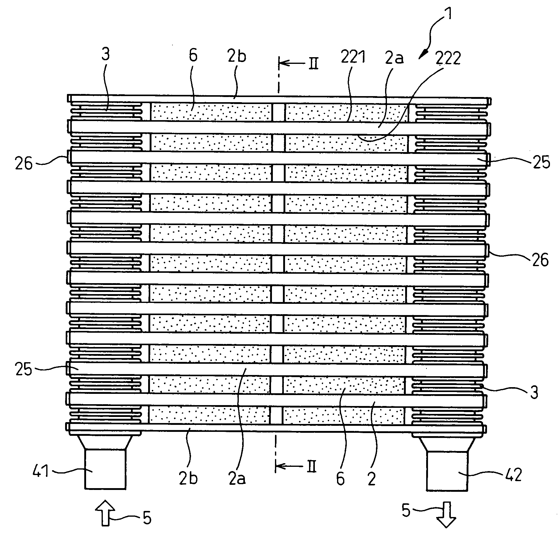
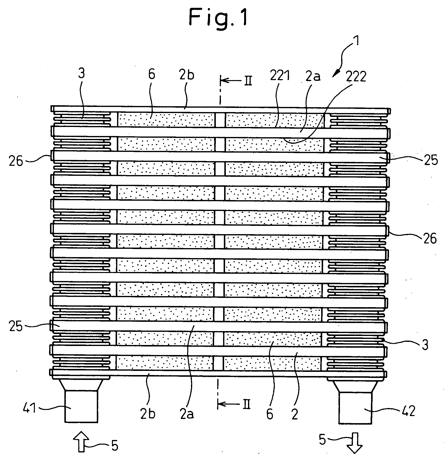
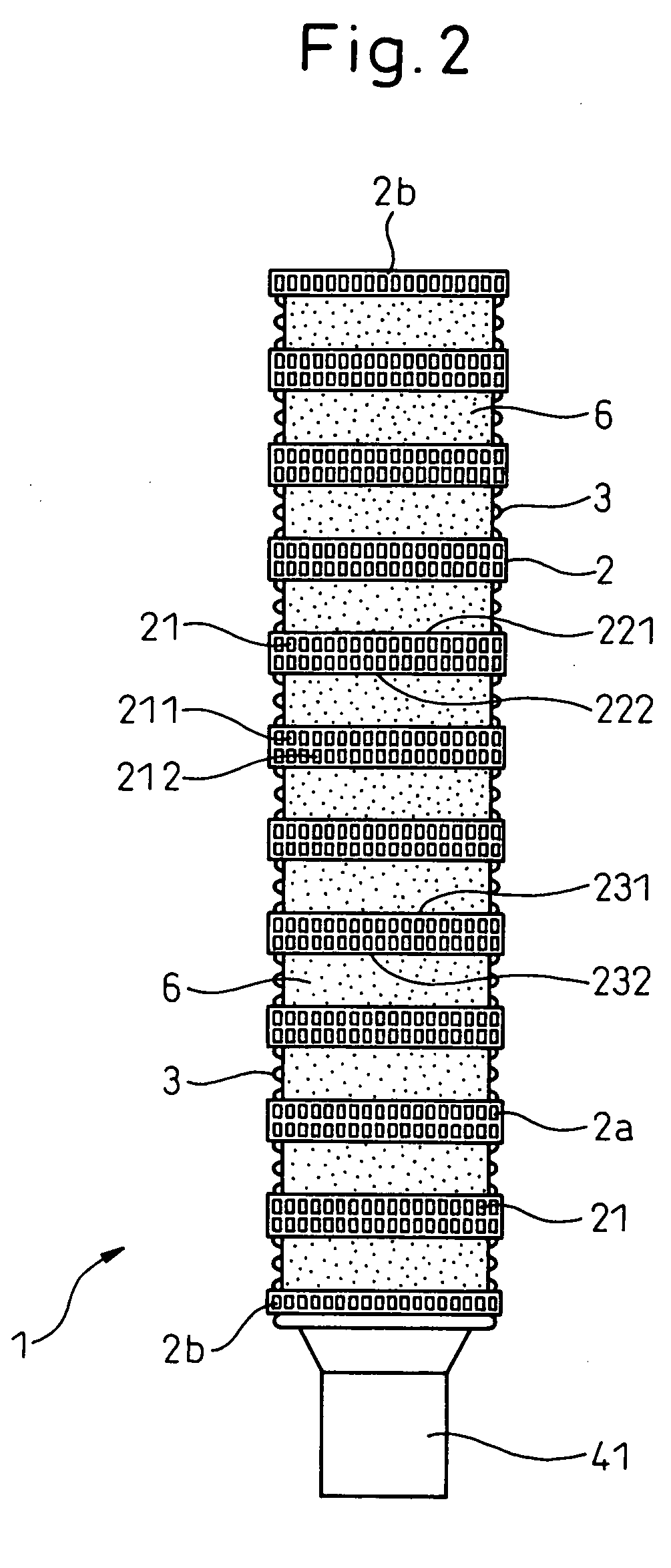
[0111] A stacked type cooler according to Embodiment 1 of the invention will be explained with reference to FIGS. 1 to 3.

[0112] The stacked type cooler 1 cools a plurality of electronic components 6 each being cooled from two of their surfaces as shown in FIGS. 1 and 2.

[0113] The stacked type cooler 1 includes a plurality of cooling tubes 2 having a flat shape and a coolant flow passage 21 for a coolant 5 to flow, and connecting pipe 3 for connecting these cooling tubes 2. The cooling tubes 2 are arranged and stacked in a plurality of layers so that the two cooling tubes 2 can sandwich the electronic component 5 at two surfaces.

[0114] The cooling tubes 2 include two outside cooling tubes 2b arranged at both ends in the stacking direction and a plurality of inside cooling tubes 2a interposed between the outside cooling tubes 2b.

[0115] The coolant flow passage 21 is formed in two stages inside cooling tube 2a in the direction of the thickness of the inside cooling tube 2a as shown...

embodiment 2

[0142] This embodiment represents an example of a stacked type cooler 1 having a construction in which a plurality of flat extrusion molding tubes 27 having a coolant flow passage 21 is stacked and bonded to one another as shown in FIG. 4 to constitute an inside cooling tube 2a.

[0143] In the extrusion molding tube 27 of this embodiment, the coolant flow passage 21 is formed in one stage in the direction of thickness. Tube walls stacked with one another constitute intermediate walls 24. The rest of the constructions are the same as those of Embodiment 1.

[0144] To use as the inside cooling tube 2a in this case, a plurality of extrusion molding tubes 27 can be stacked and bonded by forming in advance a large number of extrusion molding tubes 27 having the same shape.

[0145] The outside cooling tube 2b, too, can be constituted by use of the extrusion molding tube 27. In this case, the extrusion molding tube 27 is used alone without stacking.

[0146] Both of the inside and outside cooli...

embodiment 3

[0148] This embodiment represents an example where the inside cooling tube 2a has a so-called “drone cup” structure as shown in FIGS. 5 to 8.

[0149] In other words, the inside cooling tube 2a includes a pair of outer shell plates 201 constituting first and second tube walls 231 and 232, respectively, an intermediate plate 202 interposed between the pair of outer shell plates 201 and constituting the intermediate wall 24 and corrugated inner fins 203 interposed between the intermediate plate 202 and the outer shells 201.

[0150] First and second coolant flow passages 211 and 212 are formed between the intermediate plate 202 and the outer shell plates 201.

[0151] The inner fin 203 is formed in a greater area than an area where the electronic component 6 keeps contact with the cooling tube 2 as shown in FIGS. 5 and 7.

[0152] Two inner fins 203 are disposed in the flowing direction of the coolant 5 and a gap δ of at least 1 mm is formed between the adjacent inner fins 203.

[0153] As show...


PUM


Abstract

A stacked type cooler 1 for cooling a plurality of electronic components 6 from two surfaces of each component includes a plurality of cooling tubes 2 having a flat shape and coolant flow passage 21 for allowing a coolant to flow, and a connecting pipe 3 for communicating these cooling tubes 2. The plurality of cooling tubes 2 is arranged and stacked in such a fashion as to interpose the electronic components 6 between the cooling tubes. The plurality of cooling tubes 2 includes an outside cooling tube 2b and an inside cooling tube 2a. The inside cooling tube 2a includes at least a first coolant flow passage 211 facing a first tube wall 231 constituting a first main surface 221 of the inside cooling tube 2a and a second coolant flow passage 212 facing a second tube wall 232 constituting a second main surface 222 on the opposite side to the first main surface 221. The coolant flow passage 21 is formed into two or more stages in a direction of thickness of the inside cooling tube 2a.

Description

BACKGROUND OF THE INVENTION [0001] 1. Field of the Invention [0002] This invention relates to a cooler for cooling electronic components that generate heat from two surfaces. The invention is particularly suitable as a cooler for cooling a double-faced cooling-type electronic component for an inverter in a hybrid electric car. [0003] 2. Description of the Related Art [0004] As shown in FIGS. 20 and 21, in a stacked type cooler 9, available in the past, cooling tubes 92 are arranged in such a fashion as to sandwich a semiconductor module (electronic component) 91 between the two cooling tubes 92 in order to remove heat of the semiconductor modules 91 having built-in semiconductor devices (Japanese Unexamined Patent Publication No. 2002-26215). [0005] This stacked type cooler 9 has a construction in which the semiconductor modules 91 and the cooling tubes 92 are alternately stacked. Cooling tubes 92 stacked in this way are connected with one another through connecting pipe 93 so that ...

Claims


Application Information

Patent Timeline
IPC IPC(8): F28D1/03F28F1/04F28F9/02H01L23/473H01L25/07
CPCF28D1/0325F28D2021/0029F28F1/045F28F9/0236H01L23/473H01L2924/0002H01L25/074H01L2924/00
Inventor INAGAKI, MITSUHARUSHIRAI, MOTOHIRO
Owner DENSO CORP
Why Eureka
Try Eureka