Laminates having a low dielectric constant, low disapation factor bond core and method of making same

a technology of dielectric constant and bond core, which is applied in the direction of insulating substrate metal adhesion improvement, adhesive process with surface pretreatment, printed circuit aspects, etc., can solve the problems of reinforced or unreinforced resin systems, and achieve low dissipation factor, low dissipation factor, and easy bonding

Inactive Publication Date: 2005-06-09
PARK ELECTROCHEMICAL CORP
View PDF26 Cites 23 Cited by
  • Summary
  • Abstract
  • Description
  • Claims
  • Application Information

AI Technical Summary

Benefits of technology

[0005] According to the invention, a laminate comprises a low dielectric, low dissipation factor bond core and a resin-system layer for use in manufacturing flexible or rigid laminates that can be used in, for example, printed circuit boards. The low dielectric, low dissipation factor bond core can be a fluoropolymer or polyetherimide film or a fluoropolymer or polyetherimide prepreg, which is a reinforcement material, such as woven fiberglass or other similar fiber, impregnated with a fluoropolymer or polyetherimide. At least one, and preferably two, surfaces of the low dielectric, low dissipation factor bond core are etched or plasma or Corona discharge treated to facilitate bonding to the resin-system layer to form a low dielectric, low dissipation factor laminate. The polyetherimide core can also be a polyetherimide film or layer that is used in the manufacture of printed circuit boards, for example, a ULTEM® polyetherimide made by GE Plastics. Both of these bond core materials are characterized by low dielectric constant (Dk) and low dissipation factor (Df) properties. The bond core materials will typically have a dielectric constant less than 4.0, preferably below 3.0 and a dissipation factor less than 0.01, preferably less than 0.006.

Problems solved by technology

Further, the resin-system can be reinforced or unreinforced with conventional woven and non-woven fabrics.

Method used


Image

  • Laminates having a low dielectric constant, low disapation factor bond core and method of making same
  • Laminates having a low dielectric constant, low disapation factor bond core and method of making same
  • Laminates having a low dielectric constant, low disapation factor bond core and method of making same

Examples


examples

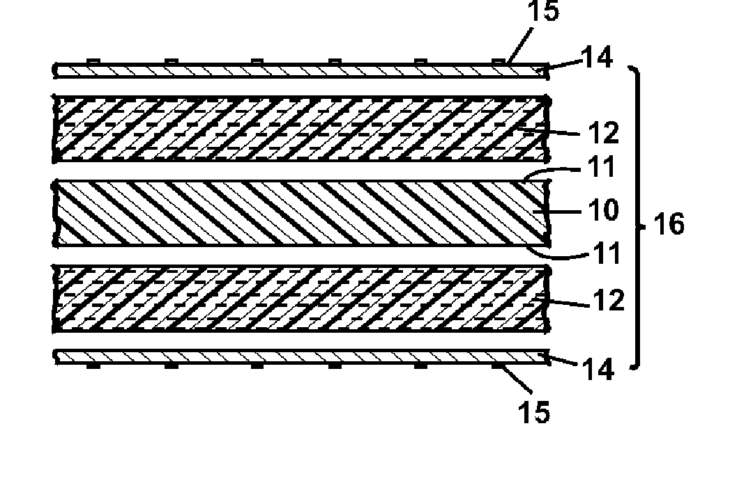
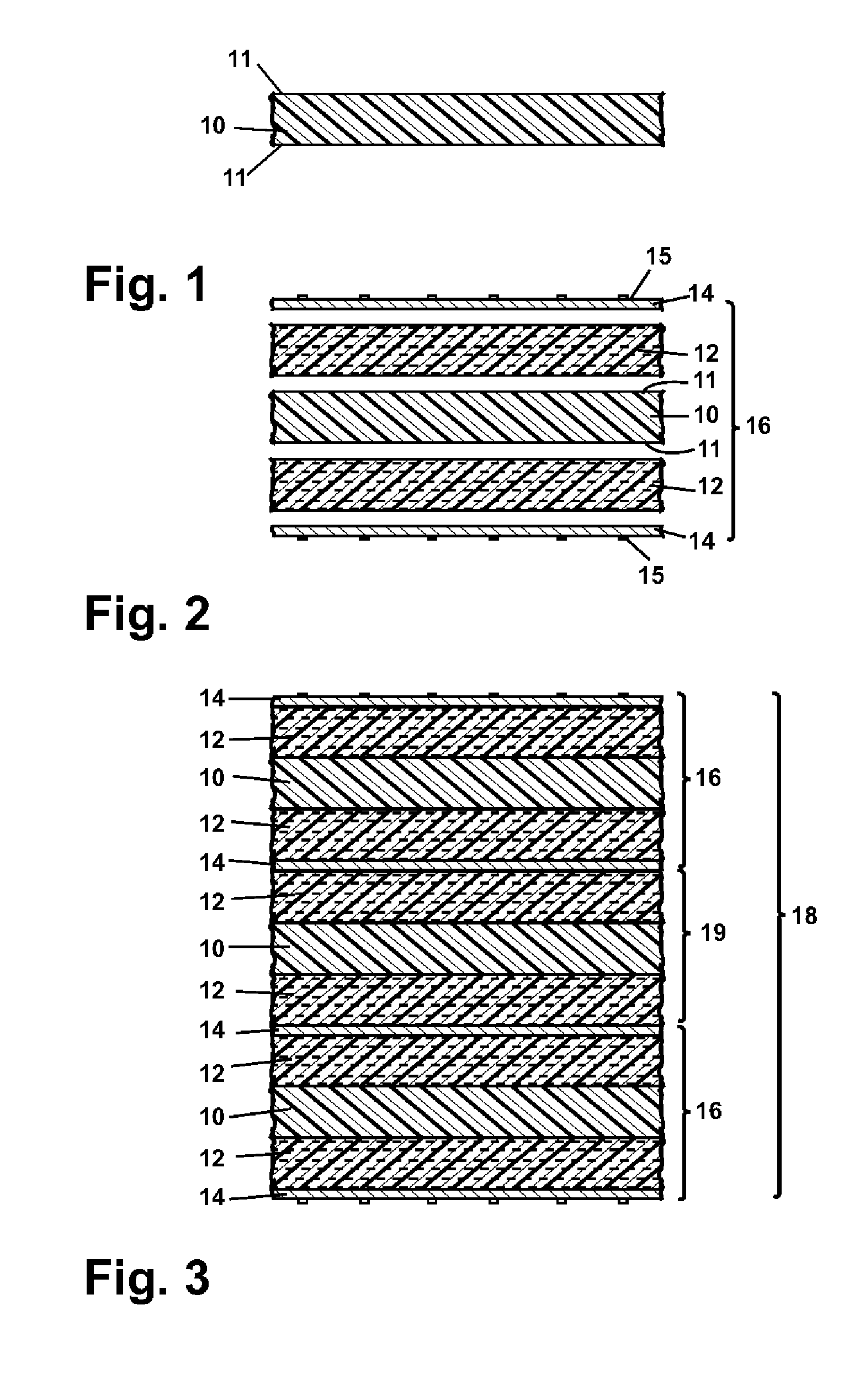
[0040] Three samples according to the invention as described above with respect to FIG. 2 were made using an etched fluoropolymer bond core comprising a PTFE film laminate core thickness of 0.020, 0.030 and 0.060 inches. A Nelco N4000-13 epoxy resin prepreg was laminated to the PTFE film. The PTFE film was subjected to chemical etching and was followed by lamination to the N4000-13 epoxy resin under standard lamination conditions and with standard lamination equipment.

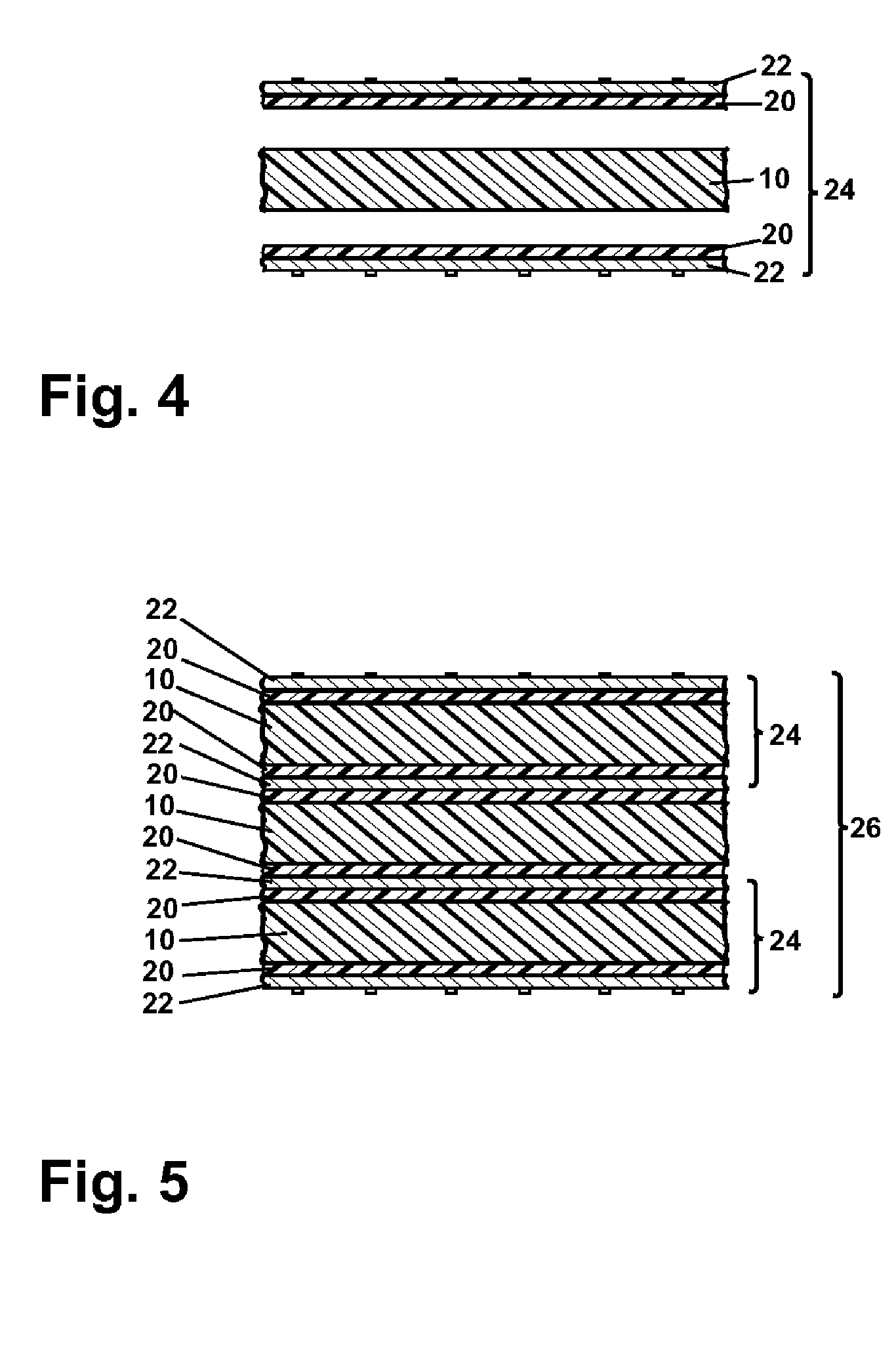
[0041] Two additional samples according to the invention as described above with respect to FIG. 2 were made using an etched polyetherimide bond core comprising a polyetherimide film with a thickness of 10 mils. A Nelco N4000-12 epoxy resin prepreg of 10 mils was laminated to each side of one of the polyetherimide films. A Nelco N4000-13 epoxy resin prepreg of 10 mils was laminated to each side of other of the polyetherimide films. The polyetherimide films were subjected to chemical etching followed by lamination to t...


PUM

PropertyMeasurementUnit
dissipation factoraaaaaaaaaa
dielectric constantaaaaaaaaaa

Abstract

Laminates have at least one resin-system layer, a low dielectric, low dissipation factor bond core having at least one surface that is treated for adhesion, such as by etching, plasma or Corona discharge or mechanical roughing to facilitate bonding to the at least one resin system layer and a conductive metal cladding on the at least one resin system layer. The bond core can be a fluoropolymer film or a fluoropolymer prepreg, having at least one etched or Corona discharge treated surface. Alternately, the bond core can be a polyetherimide film or a polyetherimide prepreg, having at least one etched or Corona discharge treated surface. The laminates are used, for example, high performance, low loss printed circuit boards. The laminates have the desired dielectric properties inherent to fluoropolymer materials and can be produced using conventional printed circuit board manufacturing processes, materials, and equipment. Methods of producing laminates are disclosed.

Description

CROSS REFERENCE TO RELATED APPLICATIONS [0001] This application claims the benefit of U.S. Patent Application Ser. No. 60 / 481, 532, filed Oct. 21, 2003, which is incorporated herein by reference in its entirety.FIELD OF THE INVENTION [0002] The invention relates to laminates having a low dielectric, low dissipation factor bond core for use, for example, in the manufacture of printed circuit boards. In one of its aspects, the invention relates to multi-layer fluoropolymer laminates. In another of its aspects, the invention relates to a fluoropolymer bond core for making multi-layer fluoropolymer laminates. In another of its aspects, the invention relates to a polyetherimide bond core for making multi-layer polyetherimide laminates. In yet another of its aspects, the invention relates to a method of making multi-layer fluoropolymer and polyetherimide laminates. In still another of its aspects, the invention relates to a method of making a fluoropolymer and polyetherimide bond core for...

Claims


Application Information

Patent Timeline
Patent Type & Authority Applications(United States)
IPC IPC(8): H05K1/03H05K3/38H05K3/46
CPCH05K1/036H05K3/381H05K3/386H05K2201/0358H05K2201/015H05K2201/0154H05K3/4626
Inventor MCKEE, SCOTTLUTTRELL, DAVEDHAENENS, MARK
Owner PARK ELECTROCHEMICAL CORP
Why Eureka
Try Eureka