Belt speed reducing apparatus for electric power steering apparatus and electric power steering apparatus

a technology of electric power steering and speed reducing apparatus, which is applied in the direction of gearing details, gearing, transportation and packaging, etc., can solve the problems of deteriorating steering feeling, uneven gear operation, and emitted tooth-struck sound, so as to promote the durability of the drive belt

Active Publication Date: 2005-06-09
NSK LTD +1
View PDF9 Cites 63 Cited by
  • Summary
  • Abstract
  • Description
  • Claims
  • Application Information

AI Technical Summary

Benefits of technology

[0085] Further, according to the electric power steering apparatus of (26), the idler pulley is arranged such that the angle of

Problems solved by technology

In a constitution of using the above-described gear speed reducing mechanism as a speed reducing mechanism, when a backlash of a mesh portion of the gear is large, there is brought about a drawback that when steering operation is reverted or the like, teeth striking sound is emitted at tooth faces.
Further, when the backlash is excessively small, there is brought about a drawback that meshed rotating operation of the gear is not carried out smoothly and a steering feeling is deteriorated or the like.
Other than the above-described, in order to set a magnitude of a backlash in a pertinent range, there is a case in which a working dimensional accuracy in fabricating a gear is promoted, or a method referred to as matching of selecting a gear on a counterpart to be meshed in accordance with a state of a finish dimension of a fabricated gear or the like, however, these methods result in increasing fabrication cost, which is not preferable.
However, when the gear is selected to determine by the above-described matching, the matching is carried out between the input gear 514 and the middle gear 516 and between the middle gear 516 and the output gear 517, which is much difficult to carry out.
Further, when a worm gear speed reducing mechanism is used, particularly in a constitution of using a saddle type worm as a worm, a three needles measuring method which is carried out in a normal worm cannot be used in measuring a finish dimension of the saddle type worm.
Thus, it is very difficult to measure the dimension of the worm and therefore, matching is carried out in operation of integrating the speed reducing mechanism and there is brought about a drawback that a number of integrating steps is increased.
Thus, it is necessary to provide bearings to a motor shaft and a gear shaft or a pulley shaft and there is a drawback of increasing a number of parts and increasing

Method used


Image

  • Belt speed reducing apparatus for electric power steering apparatus and electric power steering apparatus
  • Belt speed reducing apparatus for electric power steering apparatus and electric power steering apparatus
  • Belt speed reducing apparatus for electric power steering apparatus and electric power steering apparatus

Examples


first embodiment

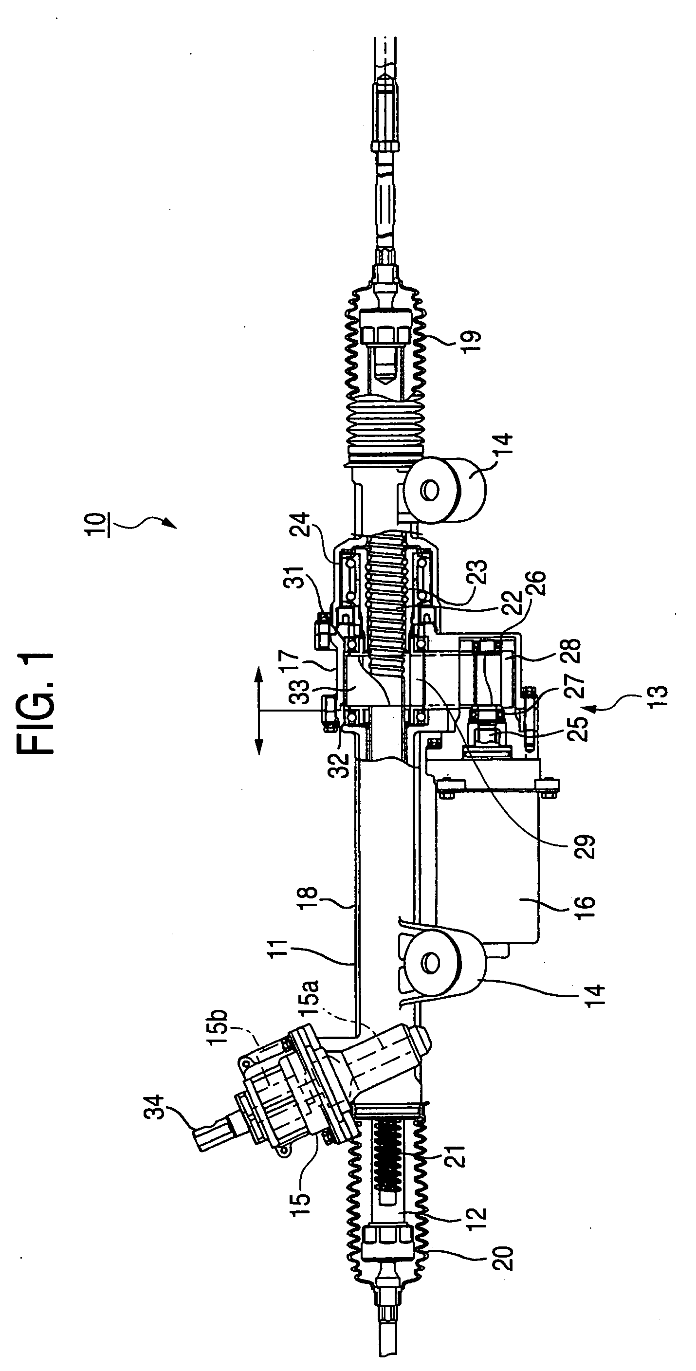
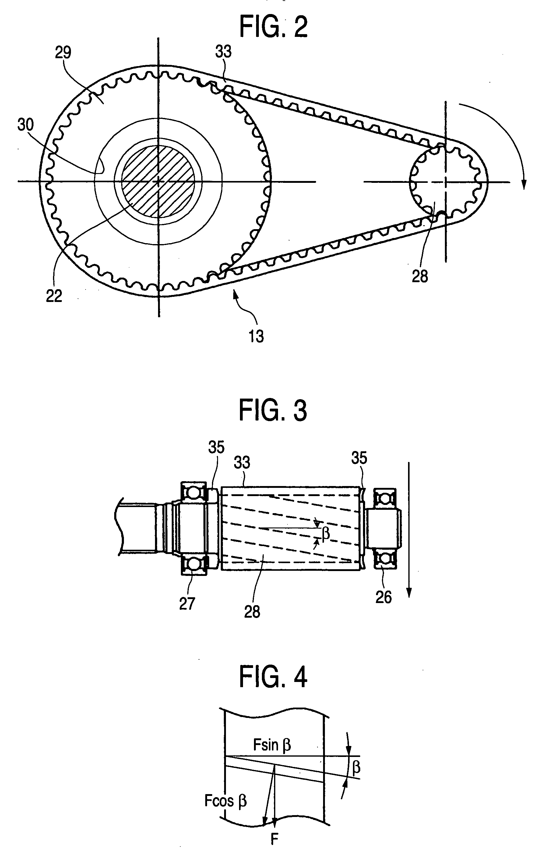
[0128] First, an explanation will be given of a belt speed reducing apparatus for an electric power steering apparatus and the electric power steering apparatus according to a first embodiment of the invention in details in reference to FIG. 1 through FIG. 4.

[0129] The electric power steering apparatus 10 according to the first embodiment is provided with the housing 11, the rack shaft 12, the belt speed reducing apparatus 13, a vehicle body attaching portion 14, a pinion portion 15 and the assisting motor 16.

[0130] The housing 11 is provided with a two divisions structure divided in two substantially at a center thereof and comprising a right housing 17 and a left housing 18. The rack shaft 12 is supported by the housing 11 movably in an axial direction but being hampered from being rotated at inside of the housing 11. Both ends of the rack shaft 12 are projected from both ends of the housing 11. The both ends are connected with a vehicle body side steering mechanism for changing...

second embodiment

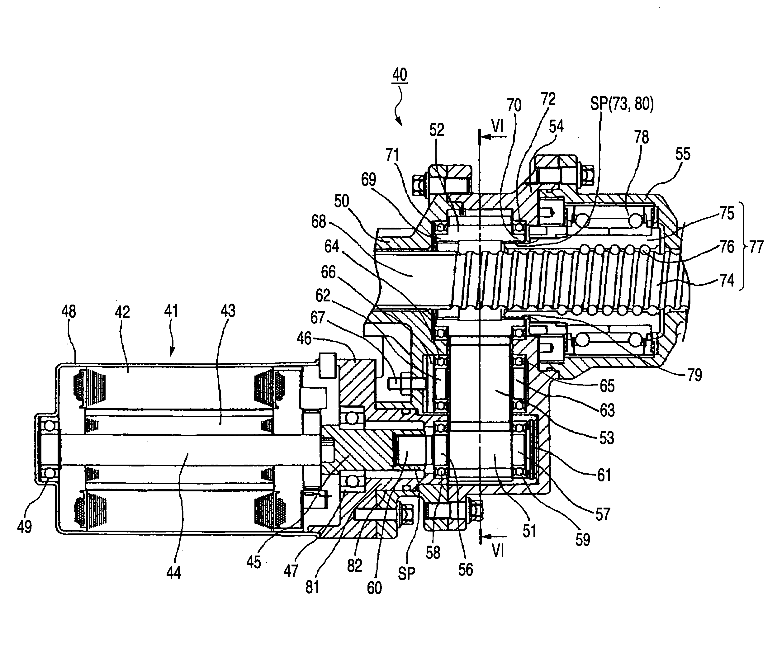
[0140] Next, an explanation will be given of an electric power steering apparatus according to a second embodiment of the invention in reference to FIG. 5 and FIG. 6. Further, according to the embodiment, a gear reducing mechanism using a helical gear is adopted.

[0141] In the electric power steering apparatus 40 according to the second embodiment, the assisting motor 41 is provided with a stator 42 and a rotor 43 and one end of the motor shaft 44 fixed to the rotor 43 is fixed with an extended portion 45. The extended portion 45 of the motor shaft 44 is supported by a bearing 47 held by the motor flange 46, other end of the motor shaft 44 is supported by a bearing 49 held by a motor housing 48 and the motor shaft 44 is rotatably supported thereby.

[0142] In order to avoid interference between the motor housing 48 and a rack shaft housing 50, a distance between axis centers of the input gear and the output gear 52 is constituted to be large and the input gear 51 and the output gear ...

third embodiment

[0154] Next, an electric power steering apparatus according to a third embodiment of the invention will be explained in reference to FIG. 7. Further, a gear speed reducing mechanism using a helical gear is adopted also in the embodiment. Further, a sectional view taken along a line VI-VI of FIG. 7 is the same as that shown in FIG. 6 and therefore, illustration thereof will be omitted.

[0155] A point of difference of the third embodiment from the second embodiment resides in that the motor shaft 44 and the input gear 51 are integrally constituted and held by three pieces of the bearings 49, 47 and 59 and that an inner ring of the bearing 59 is pressed by a nut 91 mounted to a shaft end portion of the input gear 51 and prepressure is applied to the bearing 47 and the bearing 59 to prevent rattling in an axial direction. The other constitution is the same as that of the second embodiment and therefore, the same members are attached the same notations and a detailed explanation thereof ...


PUM


Abstract

A belt speed reducing apparatus for an electric power steering apparatus includes a drive pulley having a first helical gear, a driven pulley having a second helical gear and a drive belt having a third helical gear in which a relationship of tan β<μ is established between a twist angle β of the respective helical gears and a friction coefficient μ between the first or the second helical gear and the third helical gear. Further, an electric power steering apparatus for adjusting a backlash between gears of a speed reducing apparatus brought in mesh with each other or adjusting a tension of a belt of a speed reducing apparatus.

Description

CROSS-REFERENCE TO RELATED APPLICATION [0001] This is a continuation-in-part application of PCT / JP2004 / 006079 filed on Apr. 27, 2004BACKGROUND OF THE INVENTION [0002] 1. Field of the Invention [0003] The present invention relates to a belt speed reducing apparatus for an electric power steering apparatus and an electric power steering apparatus. [0004] 2. Description of the Related Art [0005] There is known an electric power steering apparatus for a vehicle for reducing a speed of a rotational output of a motor via a speed reducing mechanism to assist steering operation as a steering assisting force. [0006] For example, in an electric power steering apparatus 500 shown in FIG. 41, a steering shaft 501 and a rack shaft 502 are brought in mesh with each other by a publicly-known pinion rack mechanism 503. Further, a motor shaft 505 of a motor 504 is rotatably supported by bearings 506, 507. [0007] The rack shaft 502 is formed with a male screw portion (spiral groove) 508. A nut 510 ro...

Claims


Application Information

Patent Timeline
IPC IPC(8): B62D5/04F16H1/08F16H7/02F16H57/12
CPCB62D5/0409B62D5/0424F16H57/12F16H1/08F16H7/023B62D5/0448
Inventor UENO, SEIJICHIKARAISHI, KAZUO
Owner NSK LTD
Why Eureka
Try Eureka