
System and method for protecting drive shaft

a technology of protection system and drive shaft, applied in the direction of machinery, process and machine control, instruments, etc., can solve the problems of limited torque applied to the drive shaft, chassis may be deformed, noise generation, etc., to reduce the output torque of the engine, and improve the durability of the drive shaft

Inactive Publication Date: 2015-05-28
HYUNDAI MOTOR CO LTD
View PDF2 Cites 3 Cited by
  • Summary
  • Abstract
  • Description
  • Claims
  • Application Information

AI Technical Summary

Benefits of technology

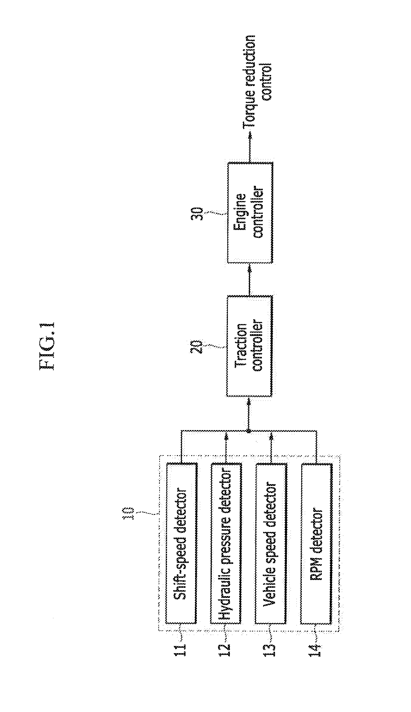
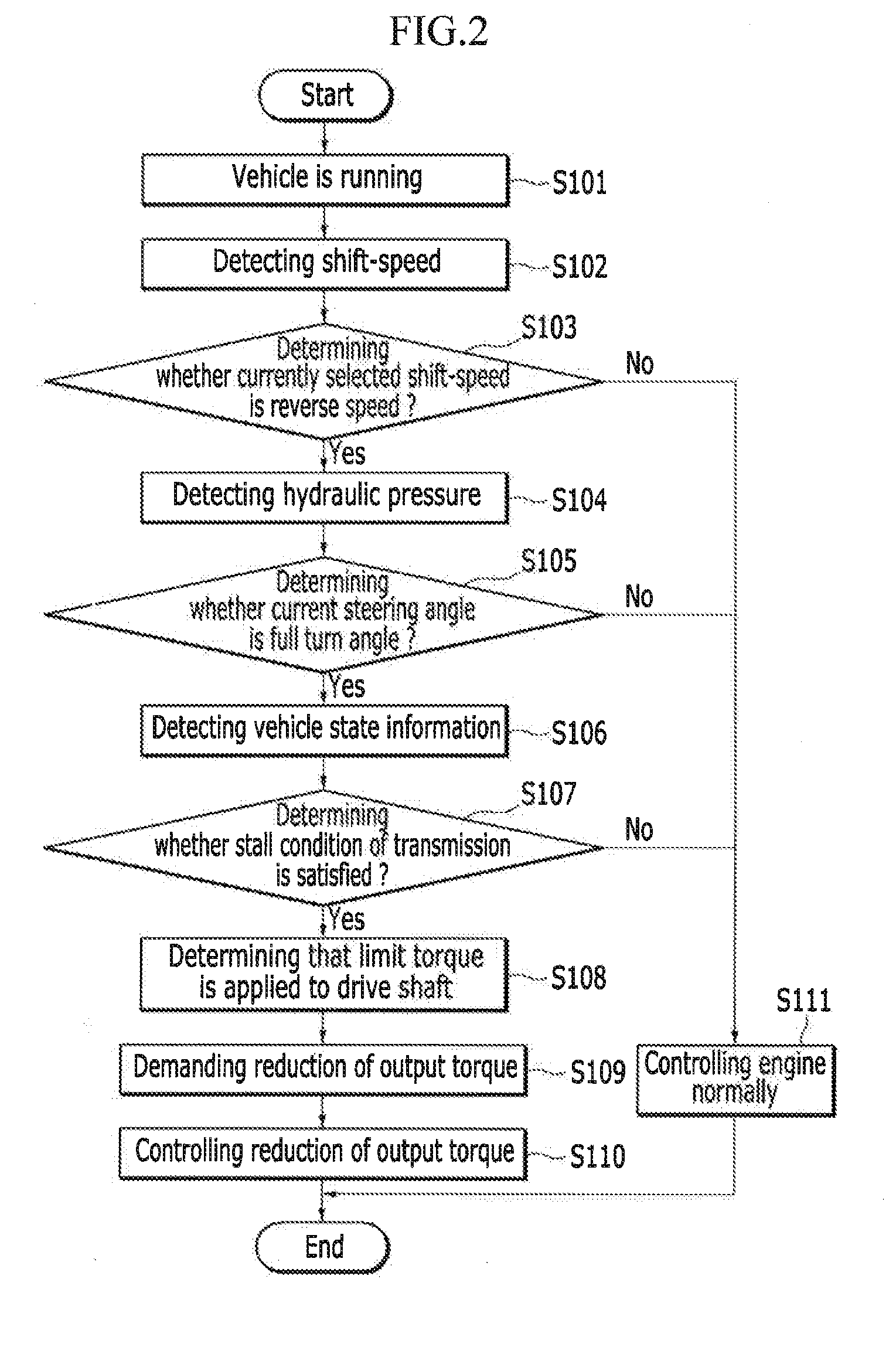
The present invention relates to a system and method for protecting a vehicle's drive shaft from damage caused by current driving conditions. The system includes a vehicle state detector that collects information such as shift speed, hydraulic pressure, and engine speed, a traction controller that analyzes this information and requests a reduction in torque if predetermined conditions are met, and an engine controller that reduces output torque of the engine based on the torque reduction request from the traction controller. The method includes determining if a reverse speed is selected, if hydraulic pressure is greater than a predetermined pressure, and if a stall condition is satisfied. This system and method can improve the durability of the drive shaft without changing the vehicle's structure or dynamics, and can be easily integrated into existing vehicles.

Problems solved by technology

Particularly, when a brake pedal and an accelerator pedal are simultaneously engaged to generate the braking force and the high engine output during the full turn and the reverse speed, the limit torque is applied to the drive shaft and noise is generated.
In extreme cases, chassis may be deformed and the drive shaft and a joint may be damaged.
Therefore, the drive shaft may be damaged during the stall of the transmission.
However, such methods increase cost and weight.
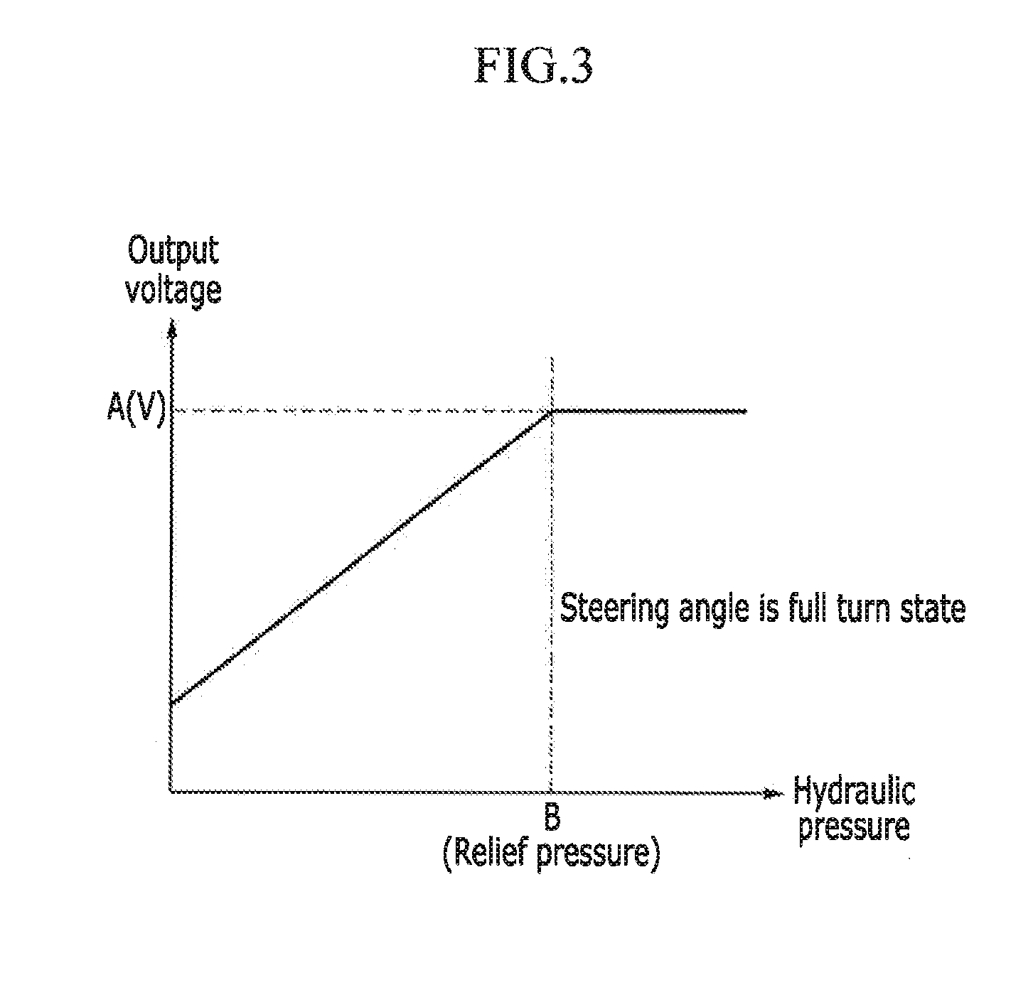
However, the steering angle sensor may only mounted to a motor driven power steering (MDPS) not to a vehicle with a HPS (Hydraulic Power Steering).
Therefore, cost may be curtailed.

Method used


Image

  • System and method for protecting drive shaft
  • System and method for protecting drive shaft
  • System and method for protecting drive shaft

Examples


Embodiment Construction

[0019]It is understood that the term “vehicle” or “vehicular” or other similar term as used herein is inclusive of motor vehicles in general such as passenger automobiles including sports utility vehicles (SUV), buses, trucks, various commercial vehicles, watercraft including a variety of boats and ships, aircraft, and the like, and includes hybrid vehicles, electric vehicles, combustion, plug-in hybrid electric vehicles, hydrogen-powered vehicles and other alternative fuel vehicles (e.g. fuels derived from resources other than petroleum).

[0020]Additionally, it is understood that the term controller refers to a hardware device that includes a memory and a processor. The memory is configured to store the modules and the processor is specifically configured to execute said modules to perform one or more processes which are described further below.

[0021]Furthermore, control logic of the present invention may be embodied as non-transitory computer readable media on a computer readable m...


PUM


Abstract

A system and method for protecting a drive shaft that include a vehicle state detector configured to detect vehicle information including currently selected shift speed, hydraulic pressure signal detected by a hydraulic pressure detector mounted to a hydraulic pressure power steering assembly, vehicle speed, and engine RPM. In addition, a traction controller is configured to analyze the vehicle information delivered from the vehicle state detector and request reduction of torque when a predetermined condition is satisfied. An engine controller is configured to reduce output torque of an engine based on torque reduction requested by the traction controller to cause the torque applied to the drive shaft to be less than a limit torque.

Description

CROSS-REFERENCE TO RELATED APPLICATION[0001]This application claims priority to and the benefit of Korean Patent Application No. 10-2012-0145731 filed in the Korean Intellectual Property Office on Dec. 13, 2012, the entire contents of which are incorporated herein by reference.BACKGROUND[0002](a) Field of the Invention[0003]The present invention relates to a system and a method that protect a drive shaft. More particularly, the present invention relates to a system and a method that protect a drive shaft which reduces output torque of an engine during reverse speed and a full turn and when a stall condition of a transmission is satisfied to prevent limit torque from being applied to the drive shaft.[0004](b) Description of the Related Art[0005]Generally, when high torque of an engine is output when braking force is generated, secondary moment of driving torque is generated due to the braking force and an angle of a drive shaft (e.g., an angle between the drive shaft and a level surf...

Claims


Application Information

Patent Timeline
Patent Type & Authority Applications(United States)
IPC IPC(8): B60K28/16B60W30/02B60W10/06
CPCB60K28/16B60W30/02B60W10/06B60W30/184B60W2510/20B60W2710/0666
Inventor CHO, JAEWANWON, YOUNG DEOK
Owner HYUNDAI MOTOR CO LTD
Learn More