

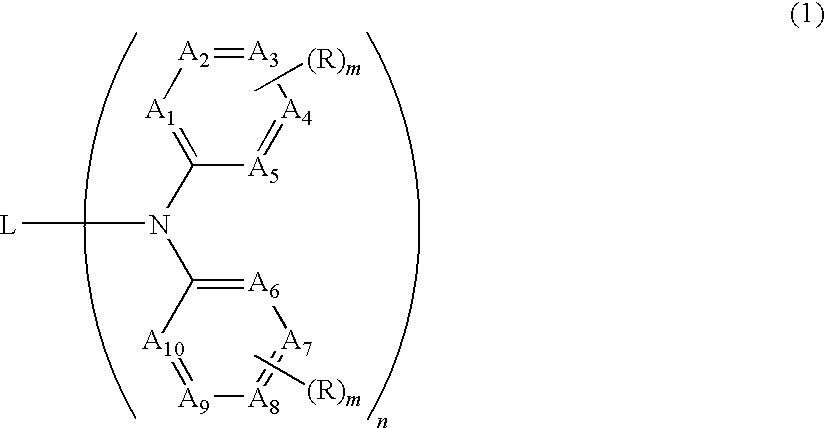
Organic electroluminescent device having specific diamine compound
a diamine compound and electroluminescent device technology, applied in the direction of discharge tube luminescnet screens, other domestic articles, natural mineral layered products, etc., can solve the problems of device efficiency or durability reduction, device needs an increased driving voltage, device achieving high efficiency and high durability, etc., to achieve high driving durability, low driving voltage, high efficiency
- Summary
- Abstract
- Description
- Claims
- Application Information
AI Technical Summary
Benefits of technology
Problems solved by technology
Method used
Image

Examples
synthesis example 1
Preparation of Compound 1
[0240]
[0241]A mixture of 1.20 g (10.0 mmol) of 2,6-diaminotoluene, 34.8 g (160 mmol) of o-iodotoluene, 3.54 g (40.0 mmol) of copper powder, 11.6 g (80.0 mmol) of potassium carbonate, 0.264 g (0.500 mmol) of 18-crown-6, and 10 ml of 1,2-dichlorobenzene was heated under reflux for 5 hours while stirring in a nitrogen atmosphere. After cooling the reaction system to room temperature, 100 ml of isopropyl alcohol was added. The solid precipitated was collected by filtration, washed successively with 5% hydrochloric acid, pure water, and methanol, and completely dissolved in 40 ml of chloroform. The insoluble matter (copper powder) was removed by filtration, and the filtrate was concentrated and recrystallized from a 1:1 mixture of toluene and hexane to give 1.35 g (56%) of Compound 1 as white crystals.
[0242]1H NMR δ (300 MHz, CDCl3, ppm): 7.15 (d, 2H), 7.08-6.97 (m, 8H), 6.95-6.89 (m, 3H), 6.74-6.66 (m, 4H), 6.52 (d, 2H), 1.94 (s, 3H), 1.81 (s, 3H), 1.50 (s, 3H)
[...
example 1
Preparation of Device 1-1
[0250]An ITO-coated glass substrate (2.5 mm×2.5 mm×0.5 mm(t)) (a product from Geomatec Corp.; surface resistivity: 10 Ω / sq) was cleaned by ultrasonication in 2-propanol, followed by UV-ozone treatment for 30 minutes. The following four organic compound layers were successively formed in the order described on the ITO film (transparent anode) by vacuum vapor deposition to the respective thicknesses described.[0251]First layer: copper phthalocyanine (CuPc) (10 nm)[0252]Second layer: NPD (see below) (40 nm)[0253]Third layer (light-emitting layer): Compound 1 and D-158 (see below) in a weight ratio of 93:7 (which composition will be referred to as “cpd. 1+7% D-158”) (30 nm)[0254]Fourth layer: BAlq (30 nm)
[0255]Subsequently, lithium fluoride and metallic aluminum were deposited in that order on the fourth layer to a thickness of 0.1 nm and 100 nm, respectively, to form a cathode.
[0256]The resulting coated substrate was transferred into a glove box purged with nit...
example 2
[0260]Organic devices were prepared in the same manner as in “Preparation of device 1-1” except for changing the composition of the light-emitting layer as shown in Table 3.
[0261]
TABLE 3MaximumRelativeLuminescenceExternalRelativeRelativeDesignationComposition ofWavelengthQuantumDrivingDrivingof DeviceLight-emitting layer(nm)EfficiencyVoltageDurabilityInventivecpd. 1 + 7% D-46466101010Device 2-1Inventivecpd. 5 + 7% D-4646610119Device 2-5Inventivecpd. 15 + 7% D-4646410106Device 2-15Inventivecpd. 20 + 7% D-464678125Device 2-20Inventivecpd. 27 + 7% D-4646710104Device 2-27Inventivecpd. 32 + 7% D-46466894Device 2-32Comparativecomparative cpd. 1 +Unmeasurable due to considerableDevice 2-17% D-46secondary light emissionComparativecomparative cpd. 4 +Unmeasurable due to considerableDevice 2-47% D-46secondary light emissionComparativecomparative cpd. 7 +4663210.1Device 2-77% D-46
PUM
| Property | Measurement | Unit |
|---|---|---|
| luminescence wavelength | aaaaa | aaaaa |
| thickness | aaaaa | aaaaa |
| Tg | aaaaa | aaaaa |
Abstract
Description
Claims
Application Information