
Solid-state laser processing apparatus and laser welding process

Inactive Publication Date: 2005-06-09
TOYOTA JIDOSHA KK +1
View PDF11 Cites 19 Cited by
  • Summary
  • Abstract
  • Description
  • Claims
  • Application Information

AI Technical Summary

Benefits of technology

[0008] The present invention has been developed in view of the aforementioned problems. It is therefore an object of the present invention to provide a solid-state laser processing apparatus which can produce laser beams exhibiting gentle intensity distribution curves less expensively. It is a further object of the present invention to provide a laser welding process for overlapped steel plates in which the solid-state laser processing apparatus is used.

Problems solved by technology

However, depending on the applications, there might arise drawbacks, because laser beams do not exhibit a uniform intensity distribution curve.
However, these lenses are very expensive.
Moreover, the lenses require long manufacturing lead times, because they are manufactured via special manufacturing processes.
Consequently, the lenses suffer from a problem in that they are less likely to be used in production lines.

Method used


Image

  • Solid-state laser processing apparatus and laser welding process
  • Solid-state laser processing apparatus and laser welding process
  • Solid-state laser processing apparatus and laser welding process

Examples


examples

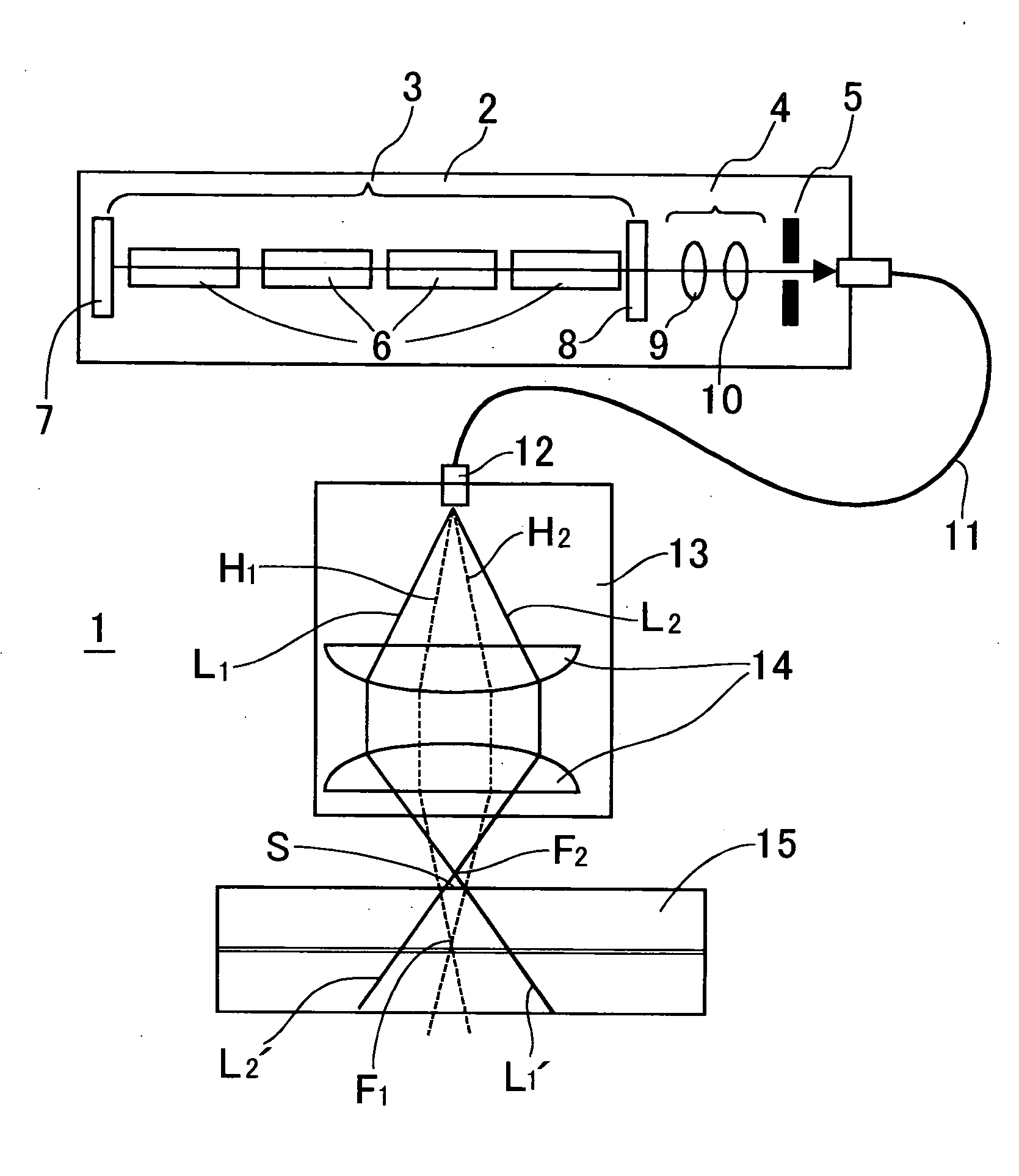
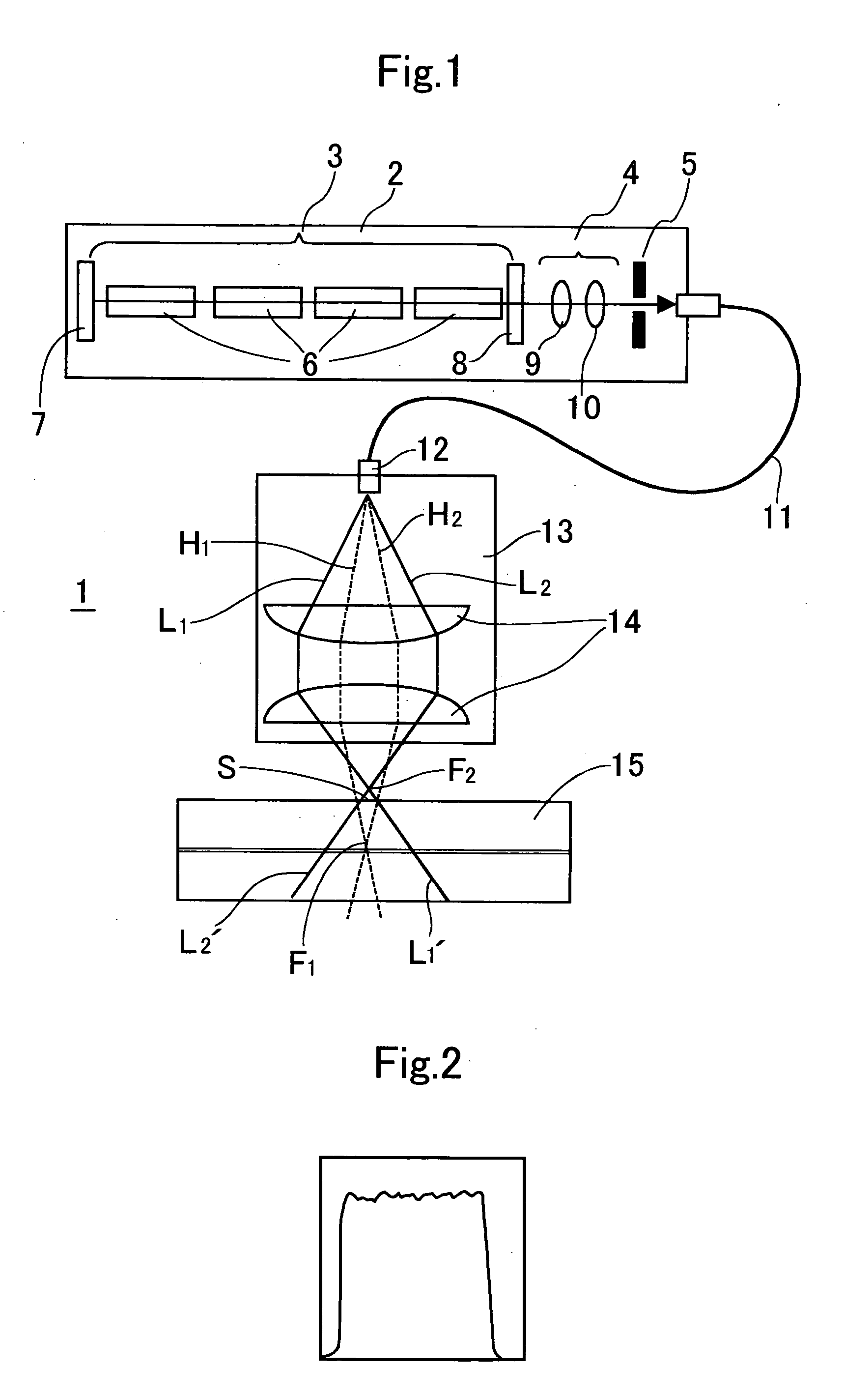
[0060] Overlapped steel plates were laser welded using the solid-state laser processing apparatus 1 illustrated in FIG. 1.

[0061] In the following examples, the beam quality of a laser beam emitted from the solid-state laser oscillator 3 was controlled to M2=105, and an optical fiber whose core diameter was 0.6 mm was used as the optical fiber 11. Moreover, the following two types of the transfer optical system 13 built into the processing head 12 were prepared: [0062] Example No. 1 comprising coupled two plane-convex lenses whose diameter was 50 mm and focal distance was 100 mm, whose spherical sides faced to each other, and which were disposed at an interval of 110 mm; and [0063] Example No. 2 comprising coupled two plane-convex lenses whose diameter was 50 mm and focal distance was 120 mm, whose spherical sides faced to each other, and which were disposed at an interval of 70 mm.

[0064] As for the steel plates, two automotive steel plates whose thickness was 0.7 mm were used. The...


PUM

PropertyMeasurementUnit
Diameteraaaaaaaaaa
Distributionaaaaaaaaaa

Abstract

A solid-state laser processing apparatus includes a solid-state laser oscillator, a laser beam diameter controller, an optical fiber, and a processing head. The solid-state laser oscillator oscillates a laser beam. The laser beam diameter controller controls a beam diameter of the laser beam, and includes an aperture. The aperture controls a beam quality of the laser beam defined by M2 so as to fall in a range of 85≦M2≦105. The optical fiber guides the controlled laser beam therein. The processing head includes a transfer optical system, and irradiates the guided laser beam to a surface of a workpiece to be processed by way of the transfer optical system.

Description

BACKGROUND OF THE INVENTION [0001] 1. Field of the Invention [0002] The present invention relates to a solid-state laser processing apparatus. Moreover, it relates to a laser welding process for welding overlapped steel plates, laser welding process in which the solid-state laser processing apparatus is used. [0003] 2. Description of the Related Art [0004] Laser beams differ from ordinary light in that they exhibit extremely small diverging angles. Accordingly, laser beams can be focused to small spot diameters, and can thereby produce high energy densities. Consequently, laser beams have been utilized in various fields, such as micro-fabrication for boring printed circuit boards and welding for steel plates. [0005] However, depending on the applications, there might arise drawbacks, because laser beams do not exhibit a uniform intensity distribution curve. Accordingly, many proposals have been made in order to improve beam qualities, for instance, as disclosed in Japanese Unexamine...

Claims


Application Information

Patent Timeline
IPC IPC(8): B23K26/073B23K26/06G02B6/42H01S3/08H01S3/10
CPCB23K26/073G02B6/4296B23K26/38B23K26/20B23K26/244
Inventor MIKATA, HIRONARIMIKAME, KAZUHISASATO, AKIOKUBA, KAZUKIFUJIKAWA, SHUICHIWATANABE, TOSHIAKI
Owner TOYOTA JIDOSHA KK
Learn More