

Methods and device for controlling pressure in reactive multilayer joining and resulting product
a multi-layer joining and reactive technology, applied in the direction of explosives, soldering devices, manufacturing tools, etc., can solve the problems of rapid rise in the temperature of reactive foils, -sensitive components can be destroyed or damaged, and material thermal damage,
- Summary
- Abstract
- Description
- Claims
- Application Information
AI Technical Summary
Benefits of technology
Problems solved by technology
Method used
Image

Examples
Embodiment Construction
[0003] 1. Field of the Invention
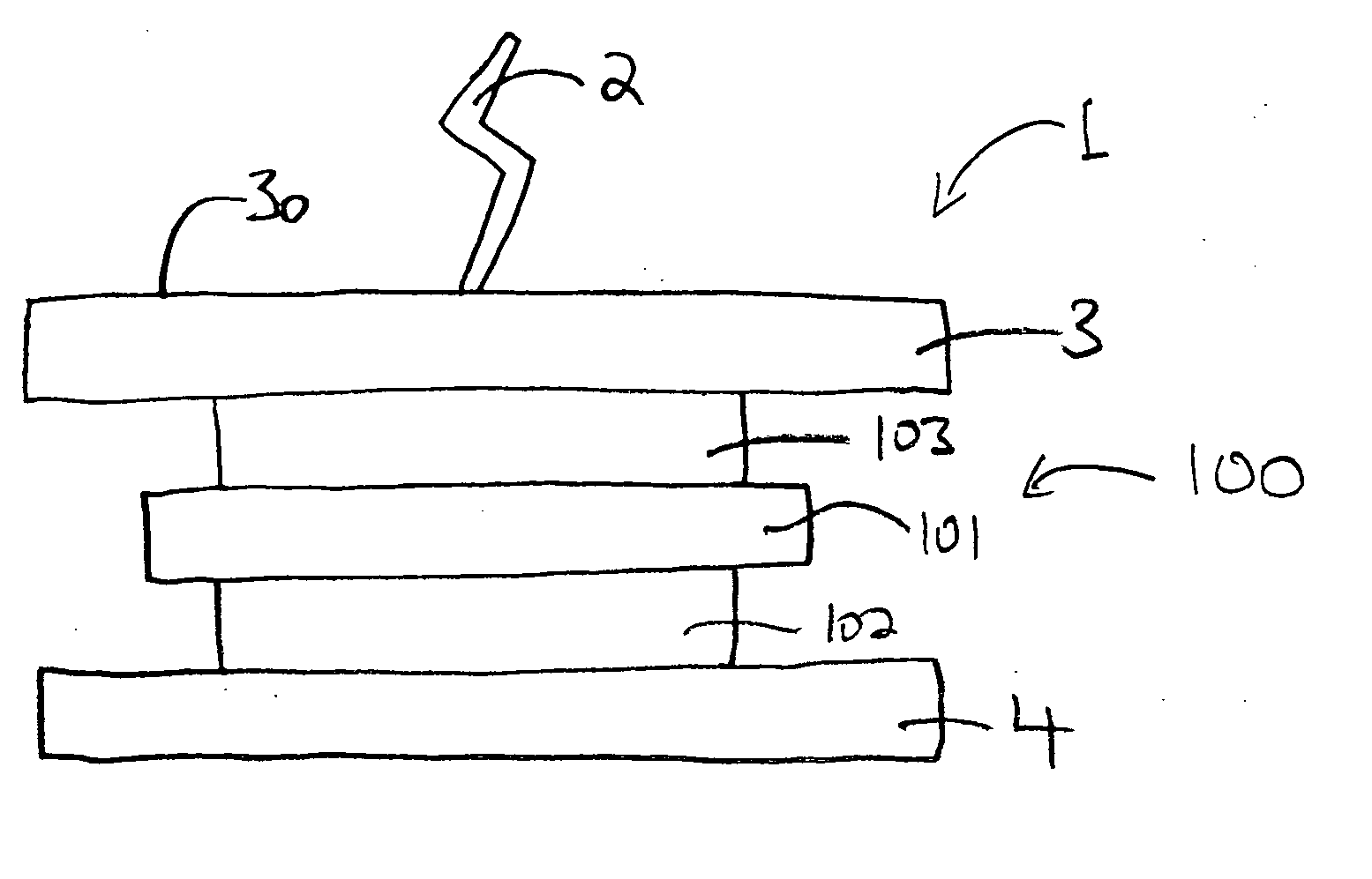
[0004] The invention includes joining two components using a reactive multilayer foil by placing the two components in contact with the reactive multilayer foil using a compliant element.
[0005] 2. Background of the Invention
[0006] Reactive multilayer joining is a particularly advantageous process for soldering, welding or brazing materials at room temperature. Examples of such joining are disclosed in the following, the entirety of all of which are incorporated herein by reference: U.S. Pat. No. 5,381,944; U.S. Provisional Patent Application No. 60 / 469,841, filed May 13, 2003; U.S. patent application Ser. No. 10 / 898,650, filed Jul. 23, 2004; U.S. Provisional Patent Application No. 60 / 201,292 filed May 2, 2000; U.S. patent application Ser. No. 10 / 843,352, filed May 12, 2004; and U.S. patent application Ser. No. 09 / 846,486, filed Apr. 18, 2002.
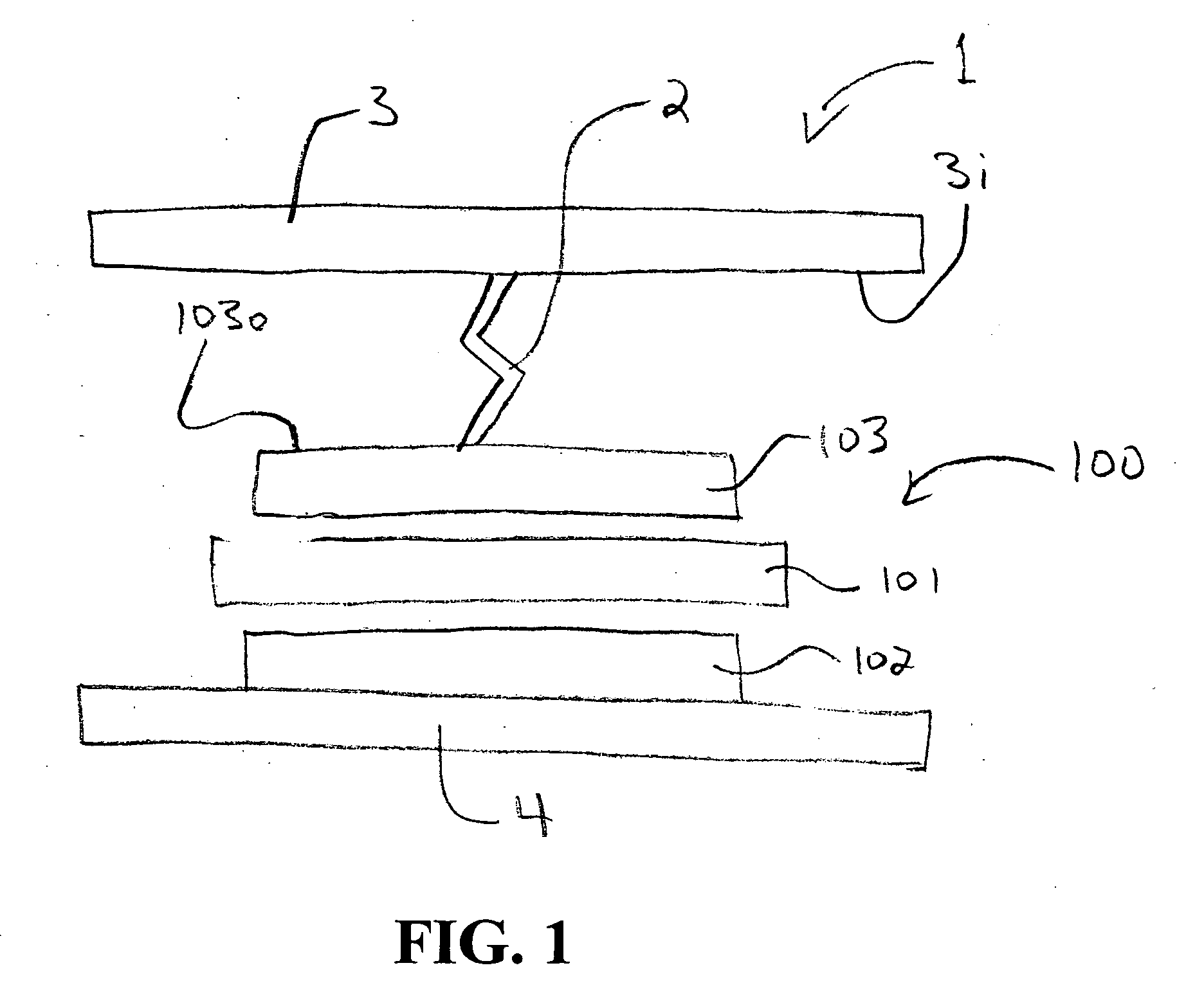
[0007] The joining process (e.g., soldering or brazing processes) is based on sandwiching a reactive multil...
PUM
| Property | Measurement | Unit |
|---|---|---|
| pressure | aaaaa | aaaaa |
| pressure | aaaaa | aaaaa |
| fusible | aaaaa | aaaaa |
Abstract
Description
Claims
Application Information