Deposition of uniform layer of desired material

a technology of desired material and uniform layer, applied in the direction of vacuum evaporation coating, solid-state device, coating, etc., can solve the problems of limited control of the nanostructural details of the coating, limited to metal, ceramics, and their composites, and general unsuitability for direct use in conventional thermal spray coating processes. achieve the effect of high speed, accurate and uniform deposition of a functional material, and high speed, accurate and precise coating of a receiver

Inactive Publication Date: 2006-12-07
EASTMAN KODAK CO
View PDF33 Cites 14 Cited by
  • Summary
  • Abstract
  • Description
  • Claims
  • Application Information

AI Technical Summary

Benefits of technology

[0027] In accordance with various embodiments, the present invention provides technologies that permit functional material deposition of ultra-small particles; that permit high speed, accurate, and uniform deposition of a functional material on a receiver; that permit high speed, accurate, and precise patterning of a receiver; that permit the creation of ultra-small features on the receiver when used in conjunction with a mask; that permit high speed, accurate, and precise coating of a receiver using a mixture of one or more nanometer sized functional material dispersed in a carrier fluid; that permit high speed, accurate, and precise coating of a receiver using a mixture of one or more nanometer sized functional material dispersed in a fluid where the nanometer sized functional materials are continuously created; that permit high speed, accurate, and precise coating of a receiver using a mixture of nanometer sized one or more functional material dispersed in a fluid where the nanometer sized functional materials are continuously created as a dispersion in the fluid in a vessel containing a mixing device or devices; and that permits high speed, accurate, and precise coating of a receiver that has improved material deposition capabilities.

Problems solved by technology

As such, synthesized nanoparticle powders are thus generally unsuitable for direct use in conventional thermal spray coating processes.
Two significant limitations of this approach are apparent: (1) it is limited to metal, ceramics, and their composites, and (2) processes occurring at the scale of micron-sized liquid particles can only provide a limited control of the nanostructural details of the coating such as porosity, size and composition of segregated regions, and defect level.
For example, desired size range for polymers is 50-200 micron: finer particles are not desirable because they easily overheat and burn in the high temperature regions of the process.
Also, the applicability of such a process where the substrate is at or near ambient atmospheric pressures is unknown but likely to be problematic: depending on the vaporization rate, it may be difficult, if not impossible, to achieve flash vaporization, and once formed, vapor may transform into particles in its flight to the substrate and that may have detrimental effect on the performance of the film in the final device.
The spray nozzle in this process is heated primarily to maintain a feathered spray pattern as the coating mixture is sprayed, not for improving the deposition efficiency of previously formed solid particles or for altering the microstructure of the coating.
A significant difficulty with coating technologies based on expansion of supercritical fluids is that particles in the range from 1-500 nm are difficult to deposit on a surface since their extremely low mass causes them to remain entrained in the expansion gas.
But these methods are still problematic: the charging and deposition efficiencies are particularly low at the low particle sizes; high performance dense films are very difficult to obtain; and since such electrostatic processes rely on the ionization of gaseous medium resulting from a high voltage point discharge across a small gap, sensitive materials can be damaged very easily.

Method used


Image

  • Deposition of uniform layer of desired material
  • Deposition of uniform layer of desired material
  • Deposition of uniform layer of desired material

Examples


example 1

Control

[0054] A SAS type particle generation process of the type disclosed in copending, commonly assigned U.S. Ser. No. 10 / 814,354 (Docket 86430) was employed to generate a desired gaseous flow stream. A nominally 1800 ml stainless steel particle formation vessel was fitted with a 4 cm diameter agitator of the type disclosed in U.S. Pat. No. 6,422,736, comprising a draft tube and bottom and top impellers. CO2 was added to the particle formation vessel while adjusting temperature to 90 C and pressure to 300 Bar and while stirring at 2775 revolutions per minute. The addition of CO2 at 60 g / min through a feed port that had a 200 μM orifice at its tip, and a 0.1 wt % solution of Tert-Butyl-anthracene di-naphthylene (TBADN: a functional material used in Organic Light Emitting Diodes) in acetone at 3 g / min, through a 100 μm tip, was then commenced and the process was allowed reach a steady state. The CO2 and solution feed ports were located close to the bottom impeller as disclosed for ...

example 2

Invention

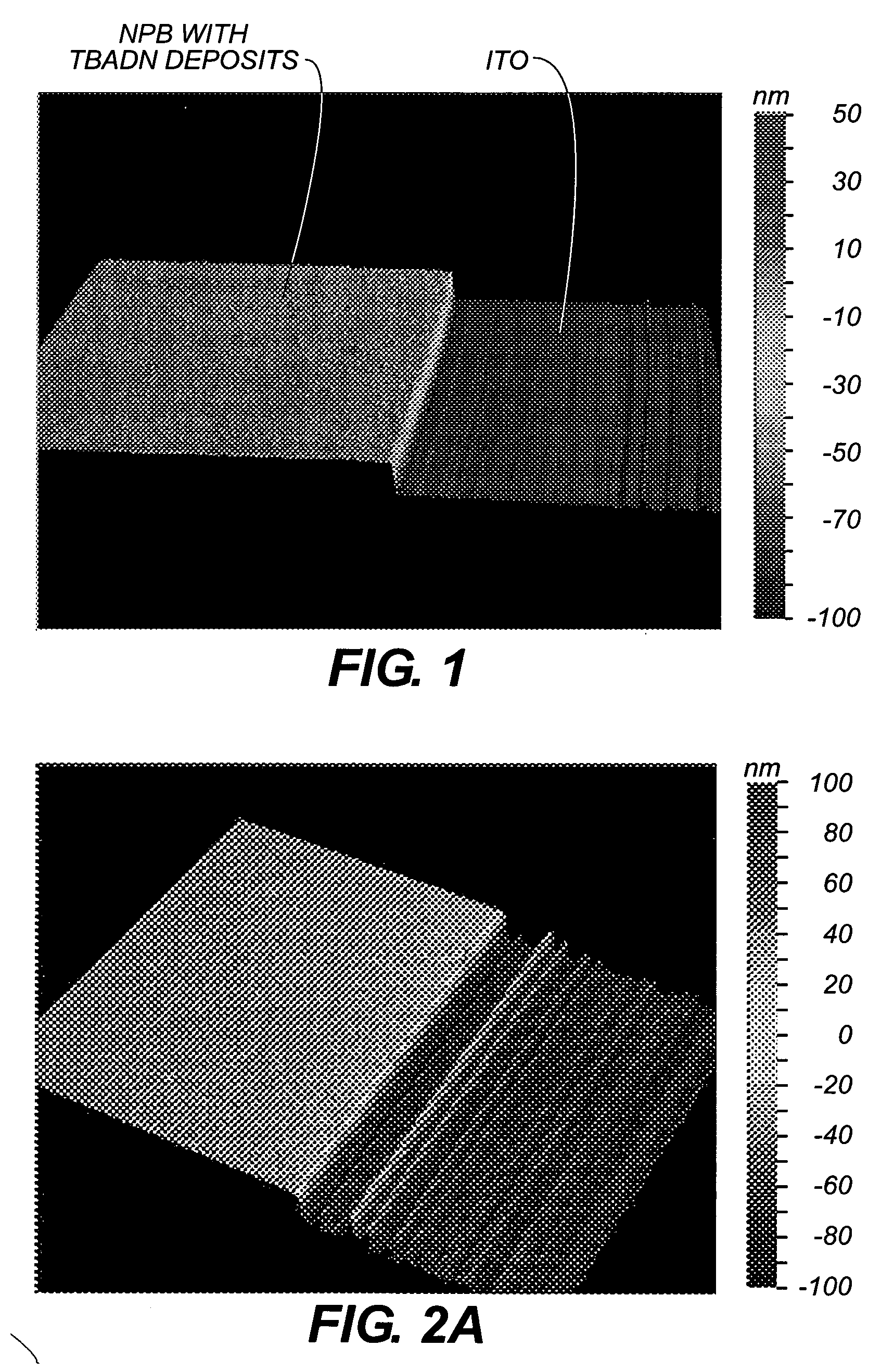
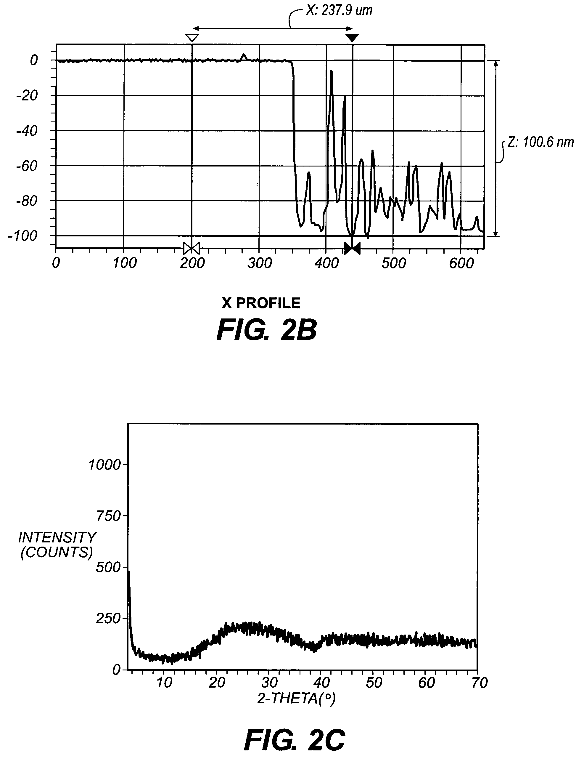
[0057] The procedure employed in Example 1 was repeated, except that the heat exchanger was powered such that the temperature of the gaseous flow exiting the slot under ambient pressure was 193 C, above the Tg of the generated TBADN particles. The resultant coating was then subjected to various characterization methods to elucidate its features. First, an edge was created carefully on the deposition surface. The coating was then coated with 2 nm thick gold film under vacuum and examined by Vertical Scanning Interferometry with a non-contact optical profilometer (WYCO NT1000 from Veeco Instruments) at a surface magnification of 10×. FIG. 2(A) shows the 3-dimensional display of the sample surface. The lower level of the signal corresponds to the ITO film surface. The higher level corresponds to the NPB layer and thin, continuous deposits of TBADN on its surface. FIG. 2(B) shows the instrument signal near the carefully created edge on the deposition surface. The lower level o...

example 3

Invention

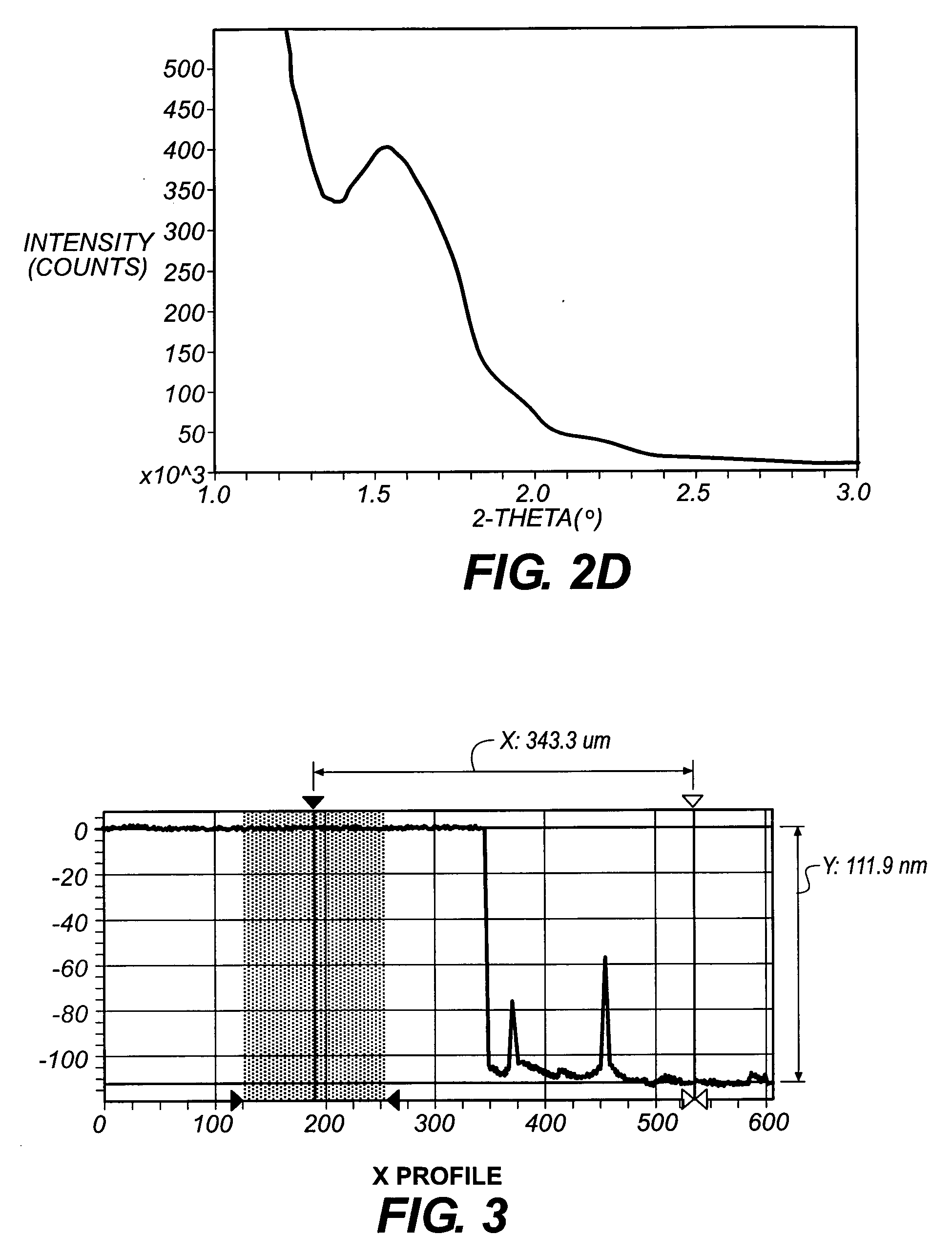
[0058] The procedure employed in Example 2 was repeated, except that the temperature of the flow at the coating slot was maintained at 222 degree C. and the substrate was passed 360 times under the coating slot. The resulting coating on the glass slide was also similarly examined by interferometry. After subtracting the thickness of underlaying NPB layer (84 nm), the TBADN film thickness was estimated to be 28 nm from FIG. 3. The surface roughness was 0.34 nm.


PUM

PropertyMeasurementUnit
volume-weighted mean particle diameteraaaaaaaaaa
volume-weighted average diameteraaaaaaaaaa

Abstract

A process for the deposition of a thin film of a desired material on a surface comprising: (i) providing a continuous stream of amorphous solid particles of desired material suspended in at least one carrier gas, the solid particles having a volume-weighted mean particle diameter of less than 500 nm, at an average stream temperature below the glass transition temperature of the solid particles of desired material, (ii) passing the stream provided in (i) into a heating zone, and heating the stream in the heating zone to elevate the average stream temperature to above the glass transition temperature of the solid particles of desired material, wherein no substantial chemical transformation of the desired material occurs due to heating of the desired material, (iii) exhausting the heated stream from the heating zone through at least one distributing passage, at a rate substantially equal to its rate of addition to the heating zone in step (ii), wherein the carrier gas does not undergo a thermodynamic phase change upon passage through heating zone and distribution passage, and (iv) exposing a receiver surface that is at a temperature below the temperature of the heated stream to the exhausted flow of the heated stream, and depositing particles of the desired material to form a thin uniform layer of the desired material on the receiver surface.

Description

CROSS-REFERENCE TO RELATED APPLICATION [0001] Reference is made to concurrently filed, co-pending application U.S. Ser. No. ______ (Kodak Docket No. 89214) by Rajesh V. Mehta et al entitled “PROCESS FOR MAKING AN ORGANIC LIGHT-EMITTING DEVICE” filed simultaneously herewith, the disclosure of which is incorporated by reference herein.FIELD OF THE INVENTION [0002] This invention relates generally to deposition technologies, and more particularly, to a technology to create a uniform thin film by delivering a flow of fine particulate material onto a receiver. BACKGROUND OF THE INVENTION [0003] Deposition technologies are typically defined as technologies that deposit functional materials dissolved and / or dispersed in a fluid onto a receiver (also commonly known as substrate etc.). [0004] Thermal spray or plasma deposition methods involve heating metallic and nonmetallic feedstock solid particles to a molten or plastic state, and propelling the heated particles onto a substrate to form a...

Claims


Application Information

Patent Timeline
Patent Type & Authority Applications(United States)
IPC IPC(8): B05D1/12
CPCB05D1/025H01L51/56H01L51/0008C23C26/00H10K71/16H10K71/00C23C14/22B05D1/02B05D1/24B82Y30/00
Inventor MEHTA, RAJESH V.JAGANNATHAN, RAMESHHOUGHTALING, BRADLEY M.LINK, ROBERTROBINSON, KELLY S.SPROUT, ROSS A.REED, KENNETH J.VERMA, ALOKMAHON, SCOTT B.GUTIERREZ, ROBLEDO O.BLANTON, THOMAS N.FORNALIK, JILL E.
Owner EASTMAN KODAK CO
Why Eureka
Try Eureka