Low voltage signal stripping circuit for an RFID reader

a low-voltage signal and reader technology, applied in the field of radio frequency identification systems, can solve the problems of inability to incorporate high-voltage-rated components, inability to cost-effectively integrate asics, and high-voltage components that are relatively expensive. achieve the effect of reducing gain

Active Publication Date: 2005-06-09
ASSA ABLOY AB
View PDF11 Cites 3 Cited by
  • Summary
  • Abstract
  • Description
  • Claims
  • Application Information

AI Technical Summary

Benefits of technology

[0016] The amplifier preferably has a first input, which is more preferably an inverting input, and a second input, which is more preferably a non-inverting input. The first and second inputs are preferably held to essentially a same voltage value. The summed signal is input to the first input and a voltage reference is input to the second input. The amplifier preferably provides a gain to the summed signal in response to the selectively distributed feedback signal to create the amplifier output signal. More particularly, the gain preferably varies as a function of a voltage of the feedback signal distributed to the summed signal. The gain is reduced when the voltage of the feedback signal distributed to the summed signal is outside a predetermined voltage range.

Problems solved by technology

Nevertheless, a reader incorporating an ASIC is only cost-effective if the number of additional electronic components needed to complete the internal electronics of the reader are minimized.
However, this results in the superposition of the smaller voltage transponder signal on the higher voltage excitation signal which requires standoff of the high voltage excitation signal from the low voltage-rated components included within the internal electronics of the reader.
Standoff of the high voltage excitation signal is generally the single most difficult function to incorporate into an ASIC of the reader because multiple high voltage-rated components, which are not permitted in an ASIC, are usually required for the standoff function.
Such high voltage-rated components are relatively expensive and cannot be incorporated into an ASIC as noted above.

Method used


Image

  • Low voltage signal stripping circuit for an RFID reader
  • Low voltage signal stripping circuit for an RFID reader
  • Low voltage signal stripping circuit for an RFID reader

Examples


Embodiment Construction

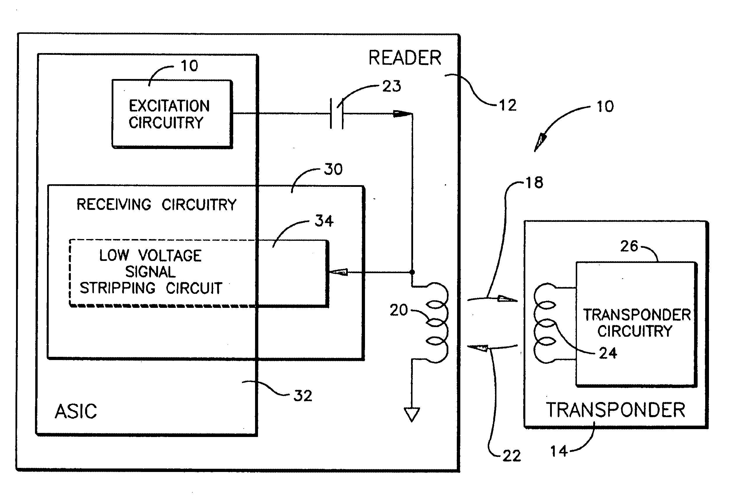
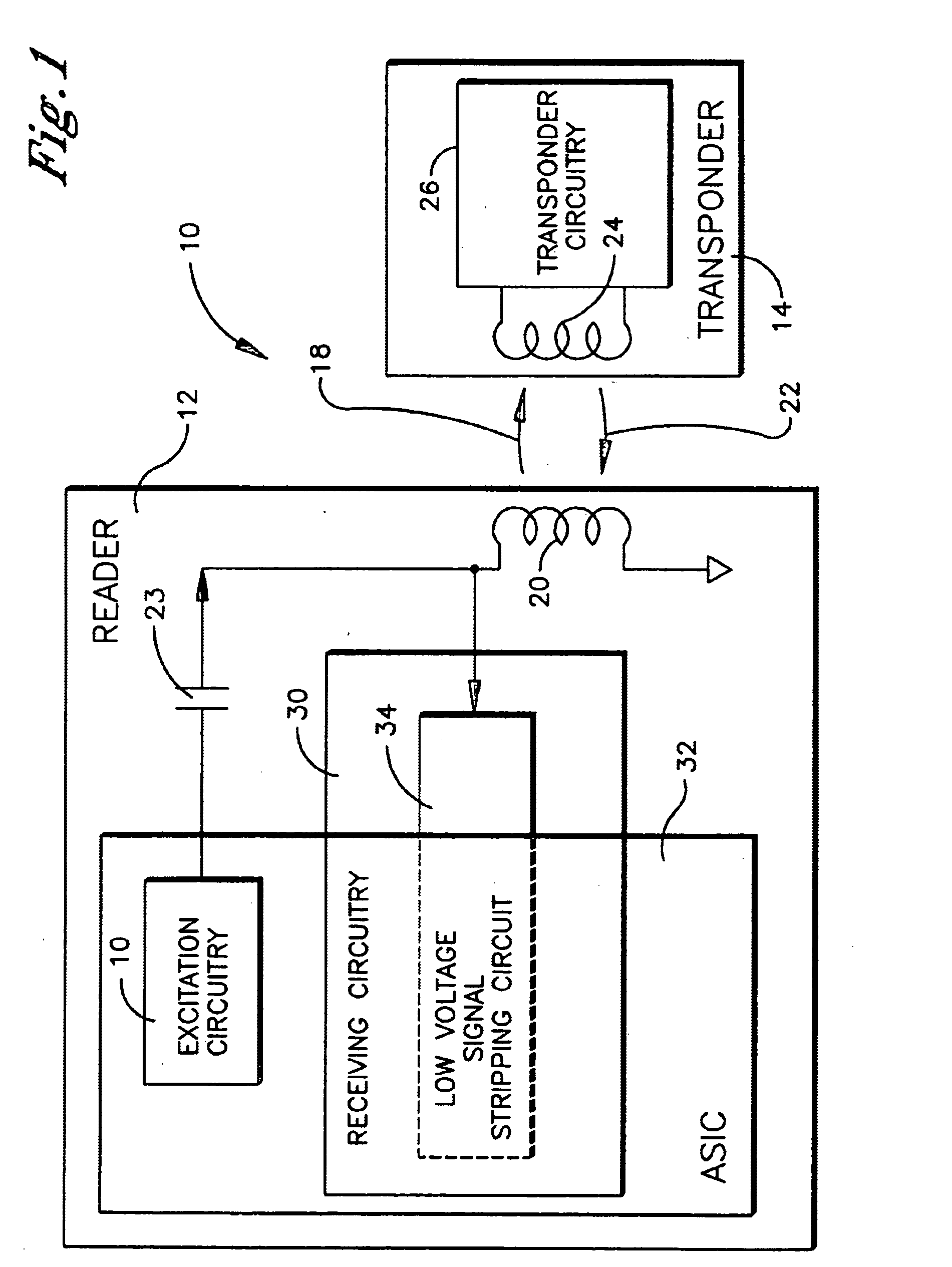
[0024] Referring to FIG. 1, a radio frequency identification (RFID) system employing an embodiment of the low voltage signal stripping circuit of the present invention is shown and generally designated 10. The RFID system 10 comprises a reader 12 and a transponder 14. The reader 12 is preferably an active device and the transponder 14 is preferably a passive device.

[0025] An “active device” is defined herein as an electrically powered device which has an internal electrical power supply, such as a rechargeable or disposable battery, or is hard wired to an external electrical power supply. The electrical power supply is physically coupled with the active device to directly supply essentially all of the electrical power required to operate the active device. Thus, the active device is continuously operational for its intended purpose upon being physically coupled with the electrical power supply.

[0026] A “passive device” is also an electrically powered device, but is not physically ...


PUM


Abstract

A reader of an RFID system has excitation circuitry for generating a higher voltage excitation signal, receiving circuitry for reading a lower voltage transponder signal and an antenna coupled with the excitation circuitry for transmitting the excitation signal and coupled with the receiving circuitry for receiving the transponder signal. The receiving circuitry includes a low voltage signal stripping circuit coupled with the antenna for isolating the transponder signal from the excitation signal preliminary to the receiving circuitry reading the transponder signal. The bulk of the components of the low voltage signal stripping circuit are low voltage components, which can be included in an application specific integrated circuit.

Description

TECHNICAL FIELD [0001] The present invention relates generally to radio frequency identification systems, and more particularly, to a low voltage signal stripping circuit for a reader of a radio frequency identification system. BACKGROUND OF THE INVENTION [0002] Radio frequency identification (RFID) systems generally consist of at least one host reader and a plurality of passive transponders, which are commonly termed credentials, cards, tags, or the like. An essential function of the host reader is to “excite” or power up the transponder. The reader transmits high voltage excitation signals into the surrounding space, which are received by a transponder proximal to the reader and which provide operational electrical power for the internal electronics of the recipient transponder. Once the transponder is powered up, it communicates information to the reader in a contactless manner. In particular, the powered up transponder transmits communication signals in the form of electromagnet...

Claims


Application Information

Patent Timeline
Patent Type & Authority Applications(United States)
IPC IPC(8): G06K7/00
CPCG06K7/0008
Inventor STEFFEN, DALE A.
Owner ASSA ABLOY AB
Why Eureka
Try Eureka