Process and device for compensating the low frequency magnetic field in an inductive signal coupling unit

a low frequency magnetic field and coupling unit technology, applied in process and machine control, automatic control of ignition, instruments, etc., can solve the problems of increased insertion loss of signal, increased bulk of coupling unit, and inability to carry out signal injection functions. achieve the effect of maximum efficiency

Inactive Publication Date: 2005-06-09
MAXLINEAR HISPANIA S L U
View PDF7 Cites 20 Cited by
  • Summary
  • Abstract
  • Description
  • Claims
  • Application Information

AI Technical Summary

Benefits of technology

[0024] The current produced by the control module is injected in the conductor by means of a compensation winding arranged on the ferromagnetic core of the coupling unit, and through a filter offering high impedance to high frequencies which prevents the high frequency signal to be injected from being affected by the injection of the compensating current.
[0025] The injection of the compensating current produces a magnetic field in the ferromagnetic core, equal and opposite to that produced by the current which is circulating through the conductor, so that saturation is avoided of the magnetic core of the inductive coupling unit, whereby insertion loss is not added and the maximum efficiency is obtained in the transmission of the signals over the electricity grid.

Problems solved by technology

Because there are high electric currents circulating through the power conductors, and therefore, the magnetic field strength around the cables is very high, the problem arises that if a ferromagnetic core is placed around the cables, the magnetic core can become saturated and unusable for carrying out the function of signal injection.
This implies an increase in the insertion loss of the signal, which is not desirable in communication applications, wherein the loss signifies an effective reduction in the range of the communications system.
To counteract this effect the usual practice is to lengthen the coupling unit in order to try to cover more flux, but this makes the coupling unit more bulky and more expensive, which is not desirable; and all this while seeking a compromise solution between size, air gap, and insertion loss.

Method used


Image

  • Process and device for compensating the low frequency magnetic field in an inductive signal coupling unit
  • Process and device for compensating the low frequency magnetic field in an inductive signal coupling unit
  • Process and device for compensating the low frequency magnetic field in an inductive signal coupling unit

Examples


Embodiment Construction

[0036] A description is made below of several embodiments of the invention, making reference to the numbering adopted in the figures.

[0037] The embodiments of the invention refer to the injection of a specific signal onto a conductor of the electricity grid, over which a low frequency current 1 is circulating, and onto which conductor a high frequency signal is desired to be injected.

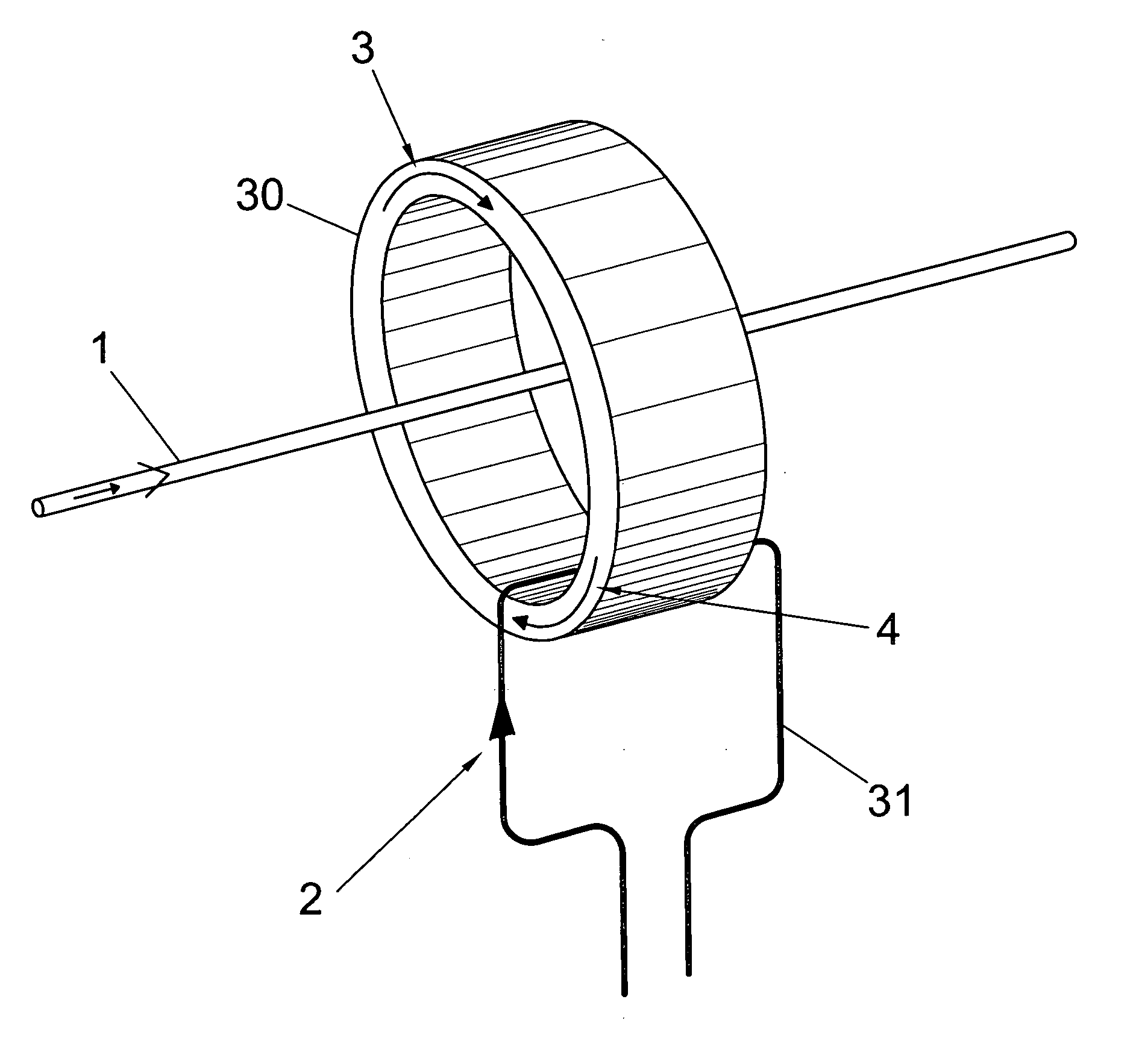
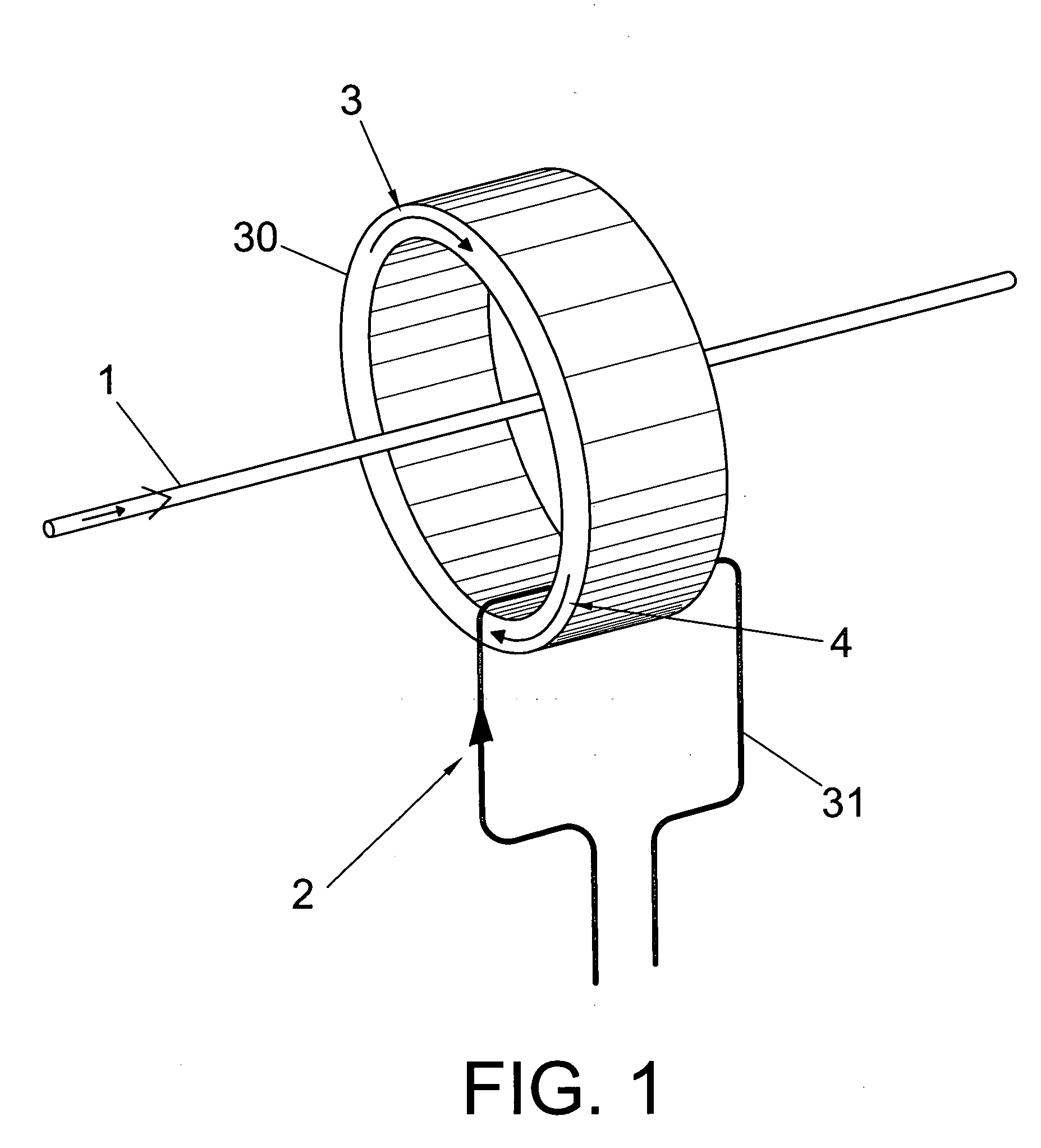
[0038] Based on FIG. 1 a generic description is provided of the problem presented in the state of the art. The employ of inductive couplers is known for injecting a determined signal onto a conductor through which a current 1 is circulating. To this end the inductive coupler is constituted by a ferromagnetic core 30 arranged around the conductor onto which one desires to inject the signal, and in which is included a winding 31 to which a current 2 is applied that produces a magnetic field 4 in the ferromagnetic core 30, which induces a current in the conductor. This device has the drawback that the cu...


PUM


Abstract

According to the invention the coupling unit comprises a ferromagnetic core (30) which encloses a conductor through which a low frequency current (1) is circulating in order to inject thereon a high frequency signal, is characterised in that current (1), circulating through the conductor or the magnetic field (3) produced in the coupling unit, is detected, and a compensating current is obtained based on the value obtained in the detection carried out, and the compensating current obtained in the coupling unit is injected through a low pass filter (9) to produce a magnetic field (4) equal and opposite to that produced by current (1) of the conductor in said coupling unit, and thereby avoiding the saturation of the magnetic care (30) without adding insertion loss. In general it is applied to communication systems which require the injection of a radiofrequency signal on a conductor, and in particular in systems which use the electricity grid as the transmission medium.

Description

CROSS REFERENCE TO RELATED APPLICATIONS [0001] The present application is a Continuation of co-pending PCT Application No. PCT / ES03 / 00283 filed Jun. 11, 2003, which in turn, claims priority from Spanish Patent Application Serial No. P200201357 filed Jun. 12, 2003. Applicants claim the benefits of 35 U.S.C. § 120 as to the PCT application and priority under 35 U.S.C. § 119 as to the said Spanish application, and the entire disclosures of both applications are incorporated herein by reference in their entireties.OBJECT OF THE INVENTION [0002] The present invention, as stated in the heading to this descriptive specification, relates to a process and a device that allow to compensate the low frequency magnetic field which is produced in an inductive coupling unit. [0003] The invention is preferably applicable for injecting high frequency signals on the electricity grid by means of an inductive coupling unit, and its object is to minimize the insertion loss of a high frequency signal on ...

Claims


Application Information

Patent Timeline
Patent Type & Authority Applications(United States)
IPC IPC(8): G01R15/18
CPCG01R15/185
Inventor BLASCO CLARET, JORGE VICENTEPOVEDA LERMA, ANTONIO
Owner MAXLINEAR HISPANIA S L U
Why Eureka
Try Eureka