Device and method of trace gas analysis using cavity ring-down spectroscopy

a technology of ring-down cavity spectroscopy and trace gas, which is applied in the field of absorption spectroscopy, can solve the problems of difficult use and impracticality for industrial applications, the inability to accurately determine the concentration of impurities using conventional cw-crds, and the yield of operational circuits reduced

Inactive Publication Date: 2005-06-09
TIGER OPTICS L L C
View PDF11 Cites 21 Cited by
  • Summary
  • Abstract
  • Description
  • Claims
  • Application Information

AI Technical Summary

Problems solved by technology

Gases such as N2, O2, H2, Ar, and He are used to manufacture integrated circuits, for example, and the presence in those gases of impurities—even at parts per billion (ppb) levels—is damaging and reduces the yield of operational circuits.
Further, the presence of impurities, either inherent or deliberately placed, in liquids have become of particular concern of late.
These methods have several features, discussed in U.S. Pat. No. 5,528,040 issued to Lehmann, which make them difficult to use and impractical for industrial applications.
Where these overlapping spectral features occur, there is no interference-free peak or baseline and the concentration of the impurity cannot be accurately determined using conventional CW-CRDS.
This system has disadvantages, however, in that the space from the laser to the cell and from the cell to the detector contribute to the signals.
Measurement error can occur if there is a mismatch or variation in the laser beam paths.
This purging increases operating cost.
Additionally, any mismatch in detectors and amplifiers cause measurement errors.
Another disadvantage in using light intensity measuring systems is that the etalon effect in the two beams must be similar for cancellation when subtracted.

Method used


Image

  • Device and method of trace gas analysis using cavity ring-down spectroscopy
  • Device and method of trace gas analysis using cavity ring-down spectroscopy
  • Device and method of trace gas analysis using cavity ring-down spectroscopy

Examples


Embodiment Construction

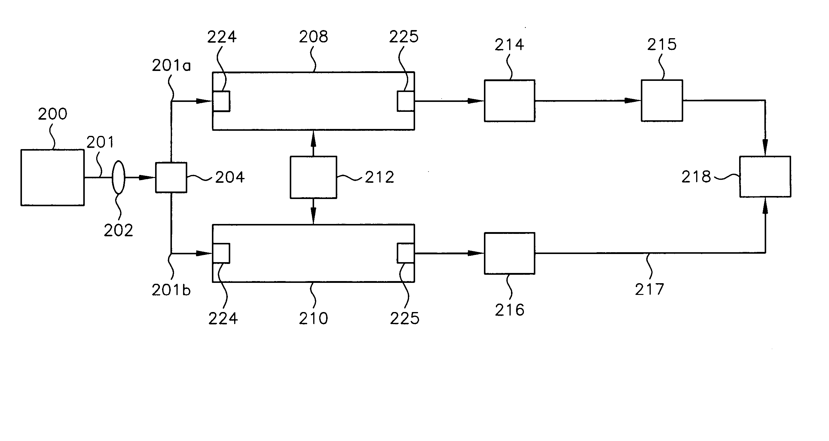
[0028]FIG. 2 illustrates a first exemplary embodiment of the present invention. In FIG. 2, a gas containing an impurity, such as an analyte, is introduced into ring-down cell 208 and a gas absent the impurity is introduced into ring-down cell 210. Ring-down cells 208, 210, which may be, but are not limited to, cavity ring-down cells, can either be filled with their respective gases or the gases may be introduced by flowing the gases through the cells. (A detailed explanation of cavity ring-down spectroscopy is not provided herein as the technology is well-known to those skilled in the art.) In one exemplary embodiment, pressure regulator 212 coupled to each of cells 208, 210 maintains substantially identical pressures within the cells.

[0029] Light 201 is emitted from tuneable light source 200, such as a CW laser, for example. Light source 200 is tuned to a predetermined frequency that is consistent with the absorption frequency of the impurity. Light 201 is collected and focused by...


PUM

PropertyMeasurementUnit
wavelengthaaaaaaaaaa
decay rateaaaaaaaaaa
concentrationaaaaaaaaaa

Abstract

An apparatus and method for analyzing an impurity on a gas is provided. The apparatus includes a first cell containing a first gas with the impurity and a second cell containing a second gas absent the impurity. A first light beam is coupled into the first cell and a second light beam is coupled into the second cell. A first detector is coupled to an output of the first cell and generates a first signal based on a decay rate of the first light beam within the first cell. A second detector is coupled to an output of the second cell and generates a second signal based on a second decay rate of the second light beam within the second cell. The concentration of the impurity is determined based on a difference between the first decay rate and the second decay rate.

Description

FIELD OF THE INVENTION [0001] This invention relates generally to absorption spectroscopy and, in particular, is directed to the detection of trace species in gases using cavity ring-down cavity spectroscopy. BACKGROUND OF THE INVENTION [0002] Referring now to the drawing, wherein like reference numerals refer to like elements throughout, FIG. 1 illustrates the electromagnetic spectrum on a logarithmic scale. The science of spectroscopy studies spectra. In contrast with sciences concerned with other parts of the spectrum, optics particularly involves visible and near-visible light—a very narrow part of the available spectrum which extends in wavelength from about 1 mm to about 1 nm. Near visible light includes colors redder than red (infrared) and colors more violet than violet (ultraviolet). The range extends just far enough to either side of visibility that the light can still be handled by most lenses and mirrors made of the usual materials. The wavelength dependence of optical p...

Claims


Application Information

Patent Timeline
Patent Type & Authority Applications(United States)
IPC IPC(8): G01J3/42G01N21/39
CPCG01J3/42G01N2021/391G01N21/39G01N21/31
Inventor YAN, WEN-BIN
Owner TIGER OPTICS L L C
Why Eureka
Try Eureka