Sealing arrangement for an axial turbine wheel

a technology of sealing arrangement and axial turbine, which is applied in the direction of liquid fuel engines, vessel construction, marine propulsion, etc., can solve the problems of significant reduction in efficiency, maintenance and service work for axial turbines not so simple as desired, and achieve the effect of convenient service and maintenan

Active Publication Date: 2005-06-09
HONDA MOTOR CO LTD
View PDF6 Cites 21 Cited by
  • Summary
  • Abstract
  • Description
  • Claims
  • Application Information

AI Technical Summary

Benefits of technology

[0005] In view of such problems of the prior art, a primary object of the present invention is to provide a sealing arrangement for an axial turbine wheel which is easy to service and maintain.

Problems solved by technology

Additionally, it is necessary to provide a sealing arrangement for the gaps of the Christmas tree or dove-tail sections as the leakage of primary and secondary air from the gaps causes a significant reduction in efficiency.
Therefore, the maintenance and service work for the axial turbine is not so simple as desired.

Method used


Image

  • Sealing arrangement for an axial turbine wheel
  • Sealing arrangement for an axial turbine wheel
  • Sealing arrangement for an axial turbine wheel

Examples


Embodiment Construction

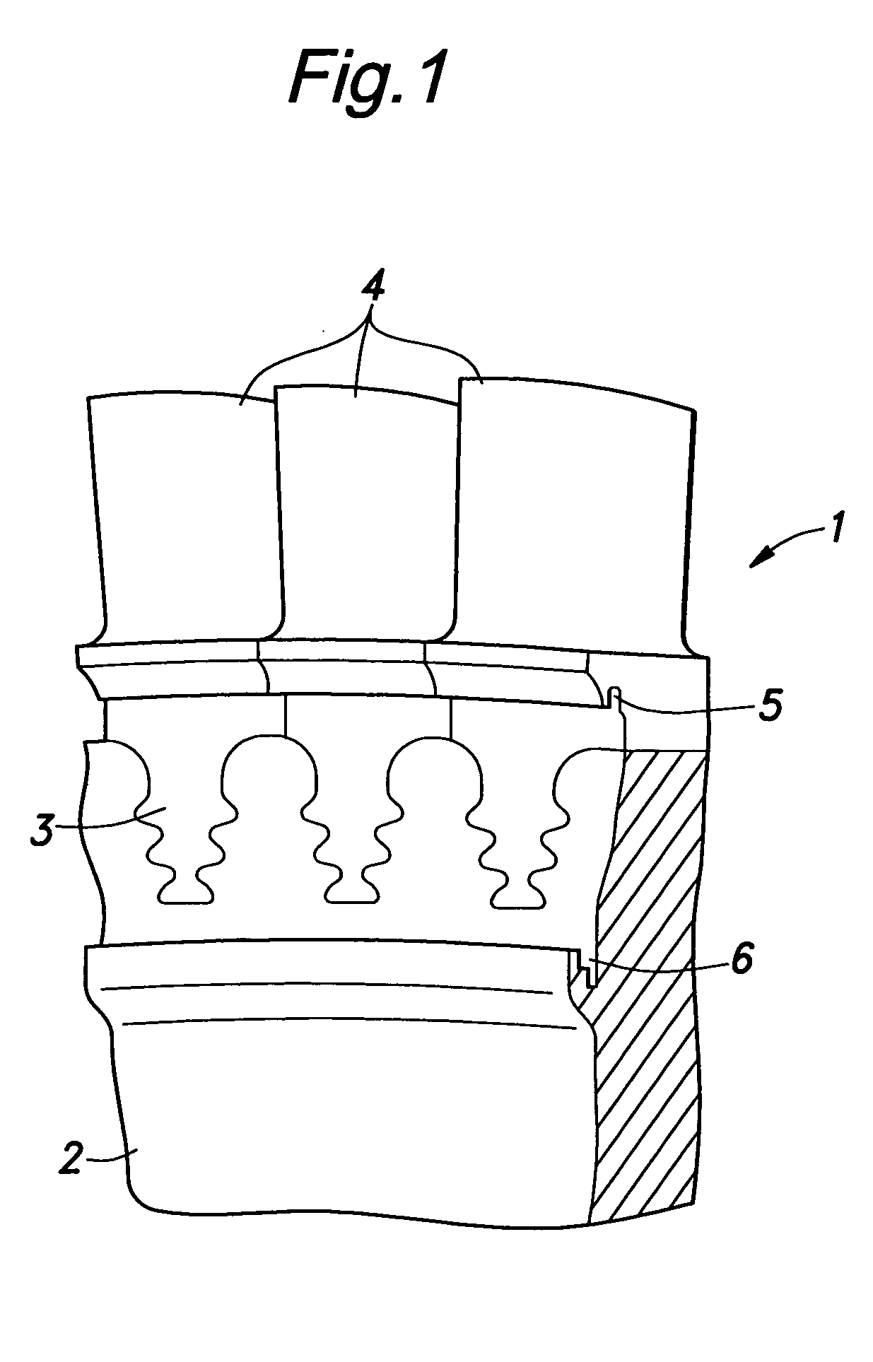
[0017]FIG. 1 shows a part of a turbine wheel assembly embodying the present invention. The turbine wheel assembly 1 comprises a rotor disk 1 and a plurality of turbine blades 4 each attached to the rotor disk 2 at a base end thereof via a Christmas tree joint 3 and extending radially from the outer circumferential surface of the rotor disk 1.

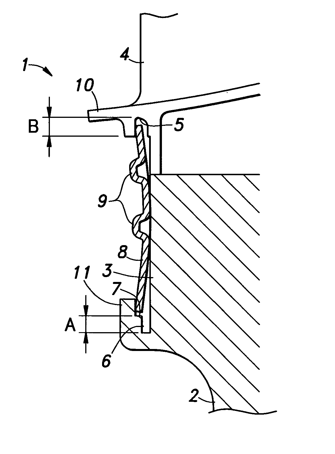
[0018] The rotor disk 2 is provided with an inner annular slot 6 which is coaxial with the rotor disk 2 and faces a radially outward direction, somewhat inward of the inner ends of the Christmas tree joints 3. An outer annular slot 5 facing radially inward in a coaxial relationship is formed in the base ends of the turbine blades 4, somewhat outward of the outer ends of the Christmas tree joints 3. These two annular slots 5 and 6 therefore oppose each other in a coaxial relationship.

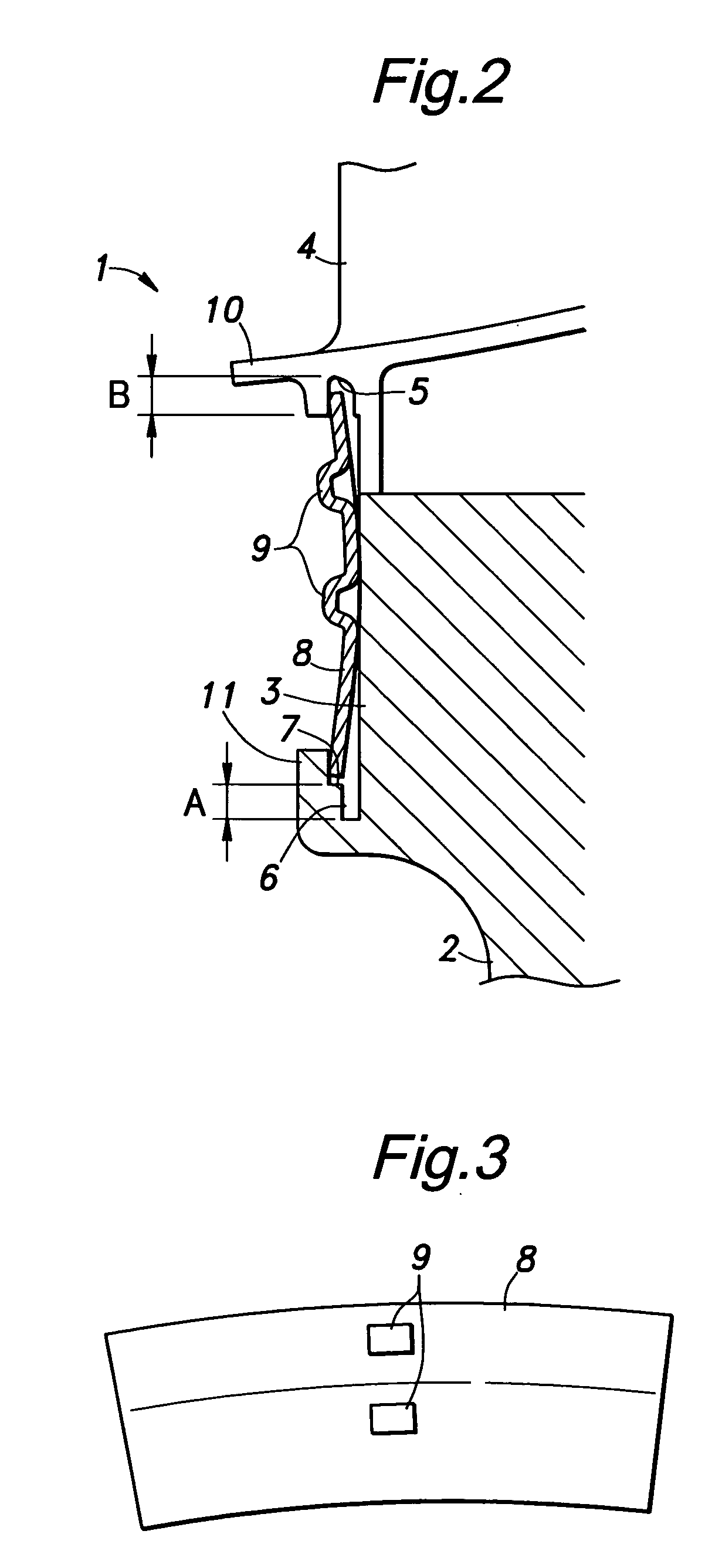
[0019] As shown in FIG. 2, the outer annular slot 5 formed in the turbine blades 4 is somewhat flared toward the axial center, and has a radial depth B when seen i...


PUM


Abstract

In an axial turbine wheel including a rotor disk and a plurality of turbine blades each having a base end retained by the rotor disk via a joint and extending radially from the rotor disk, a seal plate is received in outer and annular slots formed in the base ends of the turbine blades and rotor disk, respectively, and an annular shoulder is formed in the wall defining the inner annular slot on a side remote from the rotor disk, the annular shoulder thereby defining an inner narrow section and an outer wide section in the inner annular slot. Thus, the seal plate can be easily placed in position by first fitting the inner peripheral edge thereof in the inner narrow section of the inner annular slot, fitting the outer peripheral edge thereof in the outer annular slot until the inner peripheral edge clears the annular shoulder. Thereby, the outer and inner peripheral edges of the seal plate are received in the outer annular slot and outer wide section of the inner annular slot. The outer peripheral edge of the seal plate may abut the bottom of the outer annular slot so as to allow the seal plate to be firmly retained even when subjected to a large centrifugal force.

Description

TECHNICAL FIELD [0001] The present invention relates to a sealing arrangement for an axial turbine wheel including a rotor disk and a plurality of turbine blades extending radially from the rotor disk and each having a base end retained by the rotor disk via a joint such as a Christmas tree joint and a dove-tail joint. BACKGROUND OF THE INVENTION [0002] In an axial turbine wheel of a gas turbine engine, each turbine blade is attached to the rotor disk typically by means of an engagement between a Christmas tree section or a dove-tail section provide at the base end of the turbine blade and a corresponding recess formed in the rotor disk. Such an engagement structure provides a favorable radial retaining force, but requires a means for retaining each turbine blade against axial movement. Additionally, it is necessary to provide a sealing arrangement for the gaps of the Christmas tree or dove-tail sections as the leakage of primary and secondary air from the gaps causes a significant ...

Claims


Application Information

Patent Timeline
Patent Type & Authority Applications(United States)
IPC IPC(8): F01D11/00F01D5/30
CPCF01D11/005F01D5/3015
Inventor ONO, TAKASHITAKAMATSU, HAKARU
Owner HONDA MOTOR CO LTD
Why Eureka
Try Eureka