Golf club head with a structure for friction welding and manufacturing method therefor

a technology of friction welding and golf club head, which is applied in the field of golf club head, can solve the problems of reducing the resilience deformation capability, the fragility of the structure, and the manufacturing cost, and achieves the effects of improving the product ratio, improving the joining area, and improving the reliability of the joining

Inactive Publication Date: 2005-06-09
FUSHENG PRECISION
View PDF5 Cites 11 Cited by
  • Summary
  • Abstract
  • Description
  • Claims
  • Application Information

AI Technical Summary

Benefits of technology

[0007] An object of the present invention is to provide a golf club head that has at least one inclined or arcuate surface for friction welding on a portion of the golf club head, allowing the portion of the golf club head to be joined to another portion of the golf club head by friction welding, avoiding generation of the intermetallic layer, increasing the joining area, providing improved joining reliability, improving good product ratio, and prolonging the life of the golf club head product.
[0008] Another object of the present invention is to provide at least one inclined or arcuate surface for friction welding on one of a head body and a hosel of a golf club head, thereby joining the head body and the hosel by friction welding, providing improved joining reliability for the hosel, and increasing adjusting range of the inclination angle of the hosel.
[0009] A further object of the present invention is to provide at least one inclined or arcuate surface for friction welding on one of a head body and a weight member of a golf club head, thereby joining the head body and the weight member by friction welding, providing improved boding strength for the weight member, and providing improved joining reliability for the weight member.
[0011] In accordance with an aspect of the present invention, a golf club head includes a first portion forming a part of a head body of the golf club head and a second portion forming another part of the head body of the golf club head. The first portion is made of a first metal material and includes an abutting portion. The second portion is made of a second metal material and includes an abutting portion. At least one inclined or arcuate surface for friction welding is formed on the abutting portion of the first portion. The inclined or arcuate surface for friction welding provides the abutting portion of the first portion and the abutting portion of the second portion with improved bonding strength and increased joining area when joining the first portion and the second portion together by welding friction to form a golf club head product.
[0012] The inclined or arcuate surface for friction welding increases the abutting pressure, increases the temperature for friction welding, provides improved bonding by friction welding, avoids generation of the intermetallic layer, increases the joining area, improves the bonding strength, and improves the bonding reliability.

Problems solved by technology

Although the friction welding simplifies the manufacturing process and cuts the manufacturing cost in comparison to ordinary welding or brazing, several problems exist.
Since the metal material (e.g., stainless steel) of the flat abutting portion 14 and the metal material (e.g., titanium alloy) of the flat abutting portion 22 have poor compatibility in welding, the metallurgic structure of the intermetallic layer is detrimental to improvement of the bonding strength, resulting in a fragile structure or reducing the resilient deforming capability.
The same problem exists when using friction welding to bond two portions of the club head that are made of different metals having insufficient welding compatibility.

Method used


Image

  • Golf club head with a structure for friction welding and manufacturing method therefor
  • Golf club head with a structure for friction welding and manufacturing method therefor
  • Golf club head with a structure for friction welding and manufacturing method therefor

Examples


first embodiment

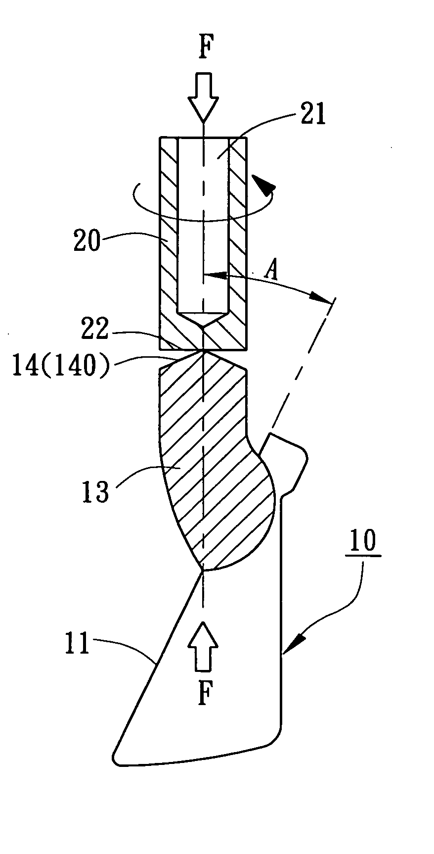
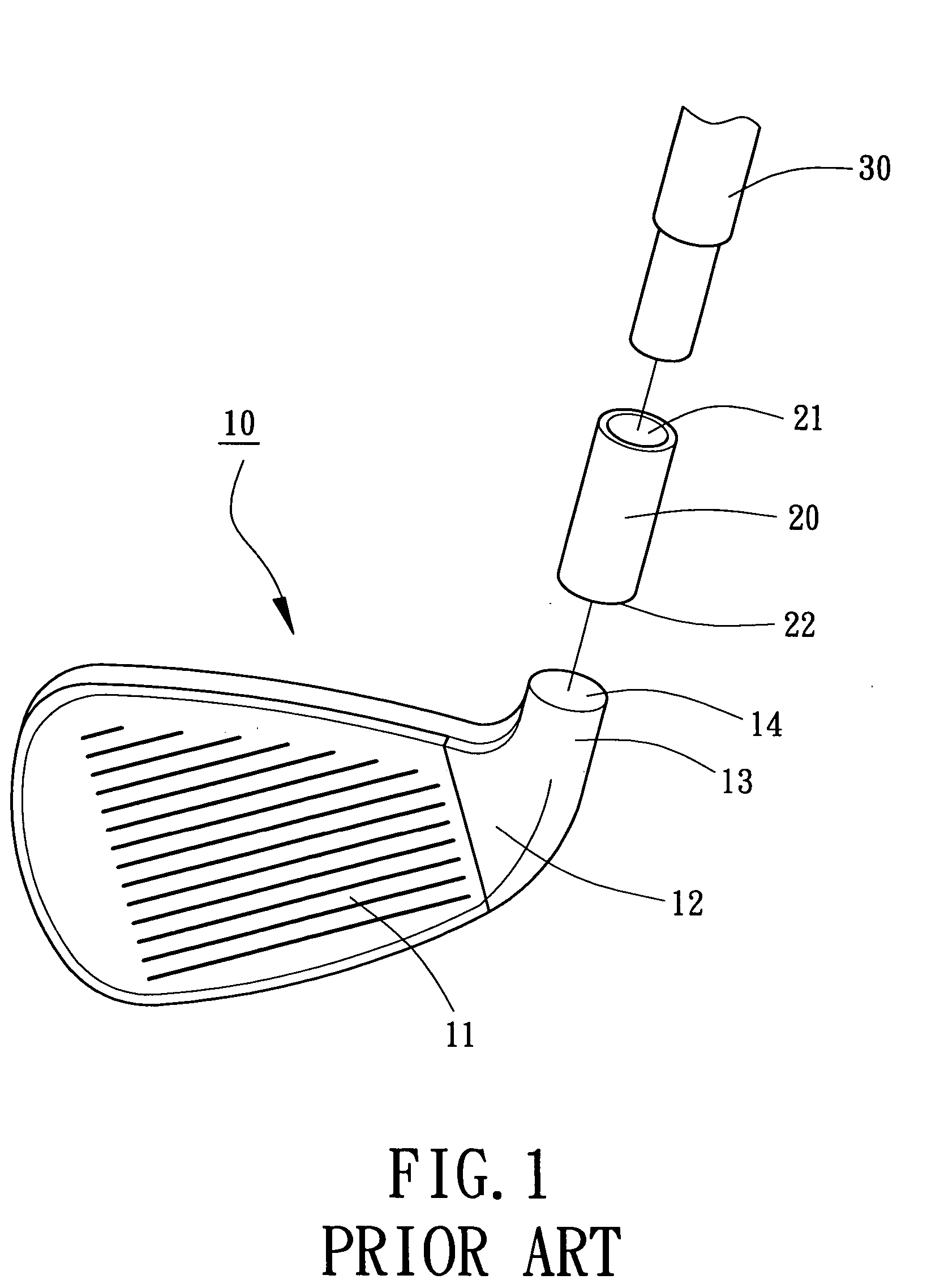
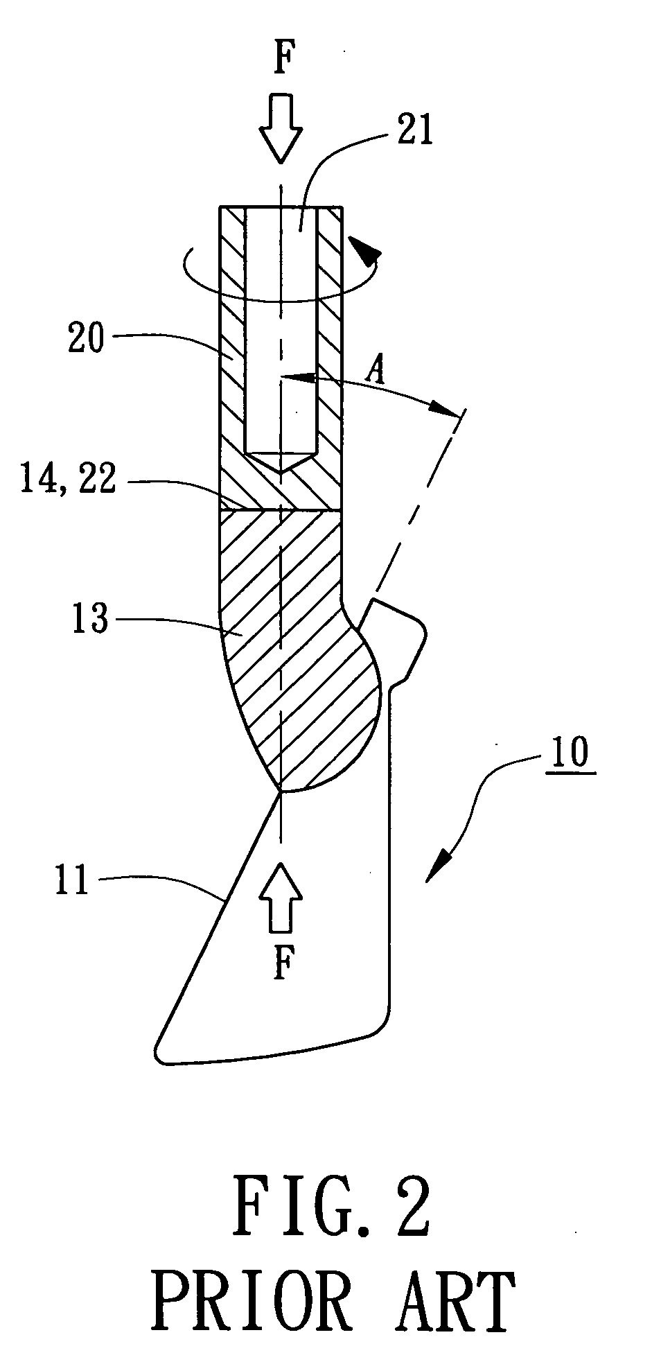
[0045] Referring to FIG. 5, a golf club head in accordance with the present invention includes a first portion, a second portion, and at least one inclined or arcuate surface for friction welding 140. In this embodiment, the first portion is a head body 10 made of a first metal material. A striking plate 11 is formed on a front side of the head body 10 for striking a golf ball. A heel 12 is formed on a side of the striking plate 11, with an extension 13 extending upward from the heel 12 and having an abutting portion 14. Preferably, the abutting portion 14 is circular.

[0046] The second portion is a hosel 20 having an engaging hole 21 in an upper part thereof for engaging with a shaft 30. The hosel 20 further includes an abutting portion 22 formed at a lower part tbereof. The hosel 20 is made of a second metal material. Preferably, the abutting portion 22 is circular.

[0047] The surface for friction welding 140 is a conic surface (i.e., inclined), as illustrated in FIGS. 5 and 6. In ...

third embodiment

[0054]FIG. 12 illustrates the present invention, wherein the abutting portion 14 of the head body 10 (the first portion) includes a first inclined surface section 140 and a second inclined surface section 142 surrounding the first inclined surface section 140. The first inclined surface section 140 is a conic face having an a cone-apex angle Θ1, and the second inclined surface section 142 is an annular face at an angle Θ2 with the first inclined surface section 140. Preferably, the cone-apex angle Θ 1 is between 90 degrees and 180 degrees. Preferably, the angle Θ2 is between 120 degrees and 180 degrees. The first and second inclined surface sections 140 and 142 increase the abutting pressure, increase the temperature for friction welding, provide improved bonding by friction welding, avoid generation of the intermetallic layer, increase the joining area, improve the bonding strength, and improve the bonding reliability. Further, the first inclined surface section 140 may include a p...

sixth embodiment

[0057]FIG. 15 illustrates the present invention. In this embodiment, the surface for friction welding is arcuate. In particular, the abutting portion 14 of the head body 10 (the first portion) includes an annular bulge 144 on a circumference thereof. The annular bulge 144, when viewed in section, is arc-shaped, semi-circular, or semi-elliptic. More specifically, given that “a” represents an apex of a section of the annular bulge 141, “b” represents two end points of the annular bulge 141 in the section, and “c” is the middle point between the apex “a” and the respective end points “b”, an angle Θ3 between two tangent lines respectively passing through the middle points “c” is between 90 degrees and 180 degrees. In brief, the arc of the annular bulge 144 has an angle between 90 degrees and 180 degrees when viewed in section.

[0058] The annular bulge 144 increases the abutting pressure, increases the temperature for friction welding, provides improved bonding by friction welding, avoid...


PUM

PropertyMeasurementUnit
angleaaaaaaaaaa
angleaaaaaaaaaa
surface roughnessaaaaaaaaaa

Abstract

A golf club head includes a first portion forming a part of a head body of the golf club head and a second portion forming another part of the head body. The first portion is made of a first metal material and includes an abutting portion. The second portion is made of a second metal material and includes an abutting portion. At least one inclined or arcuate surface for friction welding is formed on the abutting portion of the first portion. The inclined or arcuate surface for friction welding provides the abutting portion of the first portion and the abutting portion of the second portion with improved bonding strength and increased joining area when joining the first portion and the second portion together by welding friction to form a golf club head product. A method for manufacturing a golf club head by friction welding is also disclosed.

Description

BACKGROUND OF THE INVENTION [0001] 1. Field of the Invention [0002] The present invention relates to a golf club head. In particular, the present invention relates to a golf club head with a structure for friction welding. The present invention also relates to a friction welding method for manufacturing a golf head. [0003] 2. Description of Related Art [0004] A typical golf club head and a production method therefore are disclosed in, e.g., U.S. Pat. Nos. 5,769,307 and 5,885,170. As illustrated in FIGS. 1 and 2 of the drawings, which respectively correspond to FIGS. 1 and 2 of U.S. Pat. Nos. 5,769,307 and 5,885,170, a typical golf club includes a head body 10, a hose 20, and a shaft 30. The head body 10 is made of a first metal material such as stainless steel and includes a striking plate 11 on a front side thereof, with a heel 12 being formed on a side of the striking plate 11, and with an extension 13 extending upward from the heel 12 and having a flat abutting portion 14. Anothe...

Claims


Application Information

Patent Timeline
Patent Type & Authority Applications(United States)
IPC IPC(8): A63B53/02A63B53/04A63B102/32B23K20/12
CPCA63B53/047A63B53/04A63B60/00
Inventor HUANG, CHUN-YUNGCHEN, CHAN-TUNG
Owner FUSHENG PRECISION
Why Eureka
Try Eureka