
Spikeless connection and drip chamber with valve

a drip chamber and valve technology, applied in the direction of pharmaceutical containers, packaging foodstuffs, packaged goods, etc., can solve the problems of contaminating the contents of the bag, infecting the technician with aids or other diseases, etc., to facilitate the engagement of the “a” clamp and facilitate the assembly of the connector

Inactive Publication Date: 2005-06-09
RICHMOND FR M
View PDF0 Cites 75 Cited by
  • Summary
  • Abstract
  • Description
  • Claims
  • Application Information

AI Technical Summary

Benefits of technology

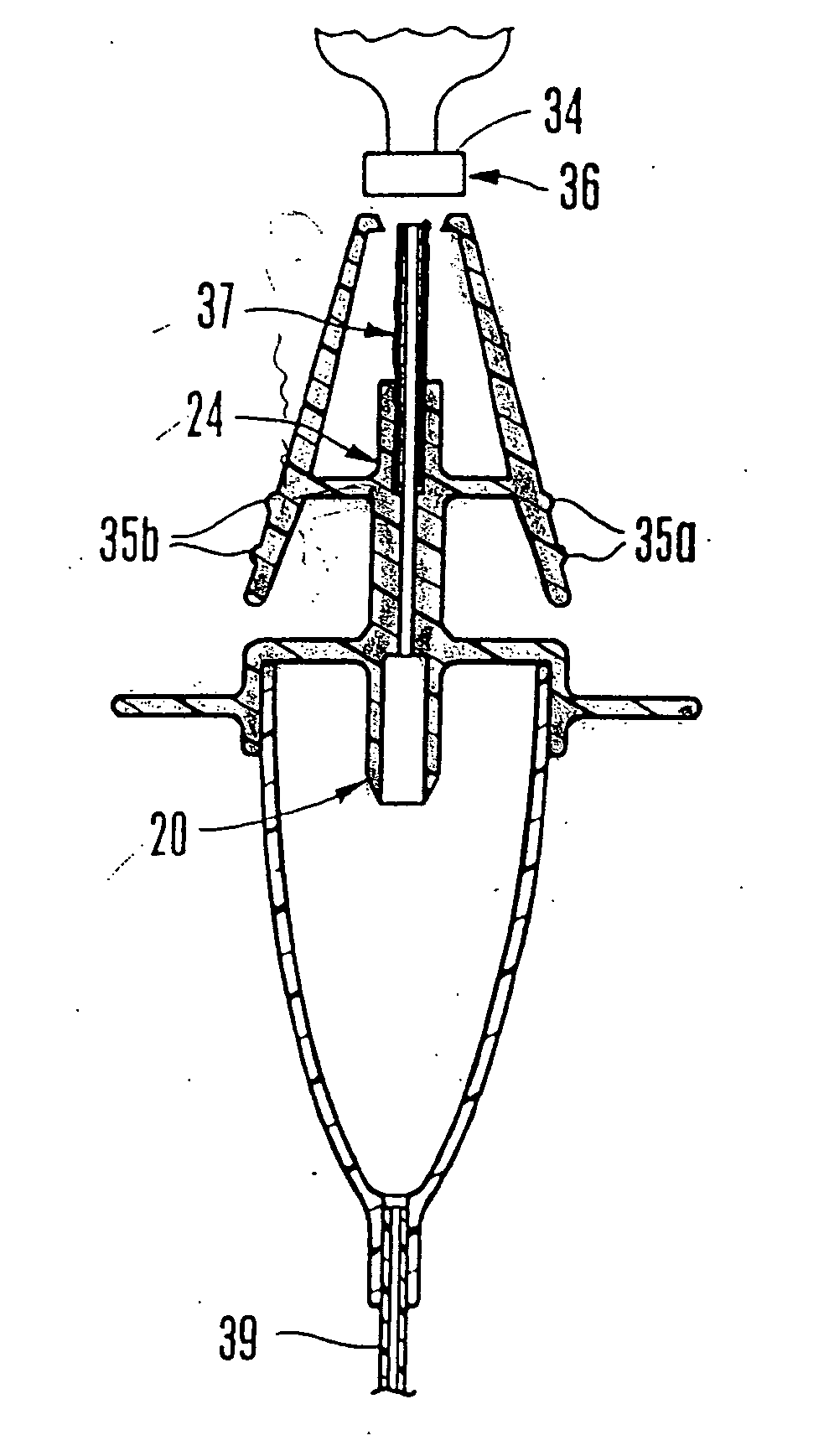
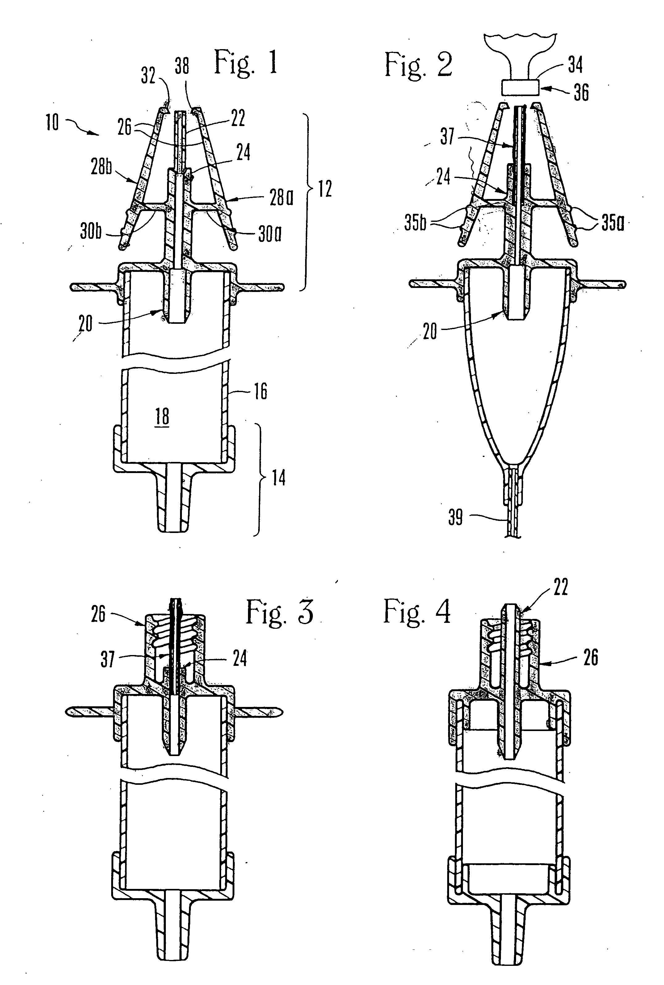
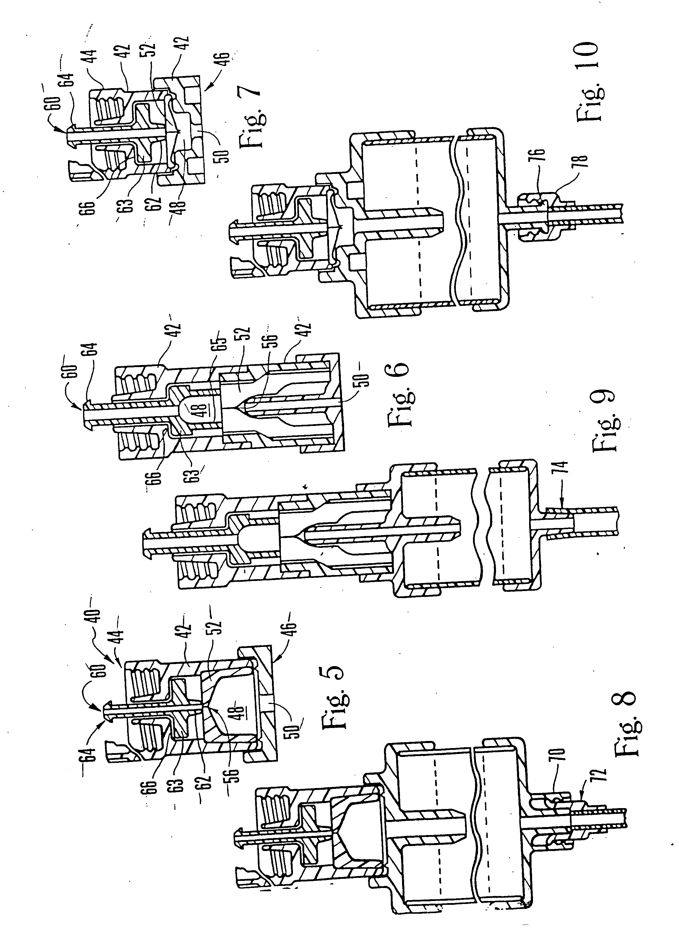
[0016] On the distal side of the container, to retain the chamber with an IV medicament connector, an attachment element is used. In one embodiment, the attachment element is configured as a threaded collar fitting. In another embodiment, the attachment element is configured as a so called “A” clamp. The “A” clamp has an open and a normal retention configuration, and is biased to the normal configuration. Preferably, the clamp includes two clamp elements, two fulcrum bars and two retaining lips. More clamp elements, fulcrum bars and lips are possible, but two of each is the most efficient. Specifically then, the clamp elements each have a distal pincer end and a proximal squeezeable end. The fulcrum bars are then attached on one side to the clamp element and on the opposite side to the cannula element or cannula holding element. The fulcrum bars are long enough such that the distal pincer ends are separated when the clamp is in the normal configuration. Ideally, the pincer ends open to facilitate easy assembly of the connector. The distal pincer ends may also be configured with a lip to engage a complementary surface on the connector. The connector can be the port of any IV device, but the port of an IV bag, or other source of fluid, is preferable. To further facilitate engagement of the “A” clamp, the lips include an angular surface which, when urged against the connector port, move the pincer ends open sufficiently to allow mating of the lip and the complementary connector surface.

Problems solved by technology

This is undesirable, particularly in the era of AIDS, because spikes, like other sharps instruments, can inadvertently puncture the bag or medical technician who is manipulating the spike and thereby potentially contaminate the bag contents or infect the technician with AIDS or other disease.

Method used


Image

  • Spikeless connection and drip chamber with valve
  • Spikeless connection and drip chamber with valve
  • Spikeless connection and drip chamber with valve

Examples


Embodiment Construction

[0035] Referring initially to FIG. 1, the drip chamber with cannula of the present invention is shown and is generally designated as 10. Preferably, the drip chamber 10 is made of a plastic (e.g. polypropylene, polyethylene, etc.). As shown, the drip chamber 10 has a distal end 12 which can be engaged with a source of fluid, such as an IV container (not shown). It is to be understood that the source of fluid can be any container suitable for holding fluid medicaments, e.g., the source can be an IV bag, vial, IV bottle, semi-rigid container, syringe, etc.

[0036] As further shown in FIG. 1, the drip chamber 10 has a proximal end 14 that can be engaged with an IV tube (shown as 39 in FIG. 2). Specifically, the IV tube 28 is advanced onto the proximal end 14 of the drip chamber 10 and is held on the proximal end 14 by solvent bonding, rf sealing, ultrasonic welding techniques, or other techniques known by those skilled in the arts.

[0037] Still referring to FIG. 1, the drip chamber 10 i...


PUM


Abstract

A drip chamber includes an elongated transparent container, and a cap. The container has open proximal and distal ends. The cap covers the distal end and further includes a drip forming tube, a cannula and an attachment element used to removably attach the chamber to a connector. The cannula extends distally away from the chamber and is surrounded by the attachment element. A pathway for fluid is established through the cannula and into the chamber.

Description

RELATED APPLICATIONS [0001] The present application is a Continuation-In-Part of and claims priority from the following co-pending U.S. patent applications: [0002] U.S. patent application Ser. No. 08 / 768,636 for an invention entitled “IV Sets With Needleless / Spikeless Fittings And Valves”, filed Dec. 18, 1996, which in turn claims priority from U.S. Pat. No. 5,645,538, filed on Mar. 12, 1996 for an invention entitled “Needleless Valve For Use In Intravenous Infusion”, which in turn claims priority from U.S. Pat. No. 5,405,333 filed on Sep. 16, 1993 for an invention entitled “Liquid Medicament Bag With Needleless Connector Fitting Using Boat Assembly.”[0003] Additionally, this application claims priority from U.S. patent application Ser. No. 08 / 751,310 for an invention entitled “Drip Chamber With Female Luer Fitting” filed Nov. 18, 1996, which in turn claimed priority from Ser. No. 08 / 377,514 for an invention entitled “Drip Chamber With Female Luer Fitting” filed Jan. 24, 1995, which...

Claims


Application Information

Patent Timeline
IPC IPC(8): A61J1/00A61J1/05A61J1/10A61J1/20A61M5/14A61M39/26A61M39/28
CPCA61J1/10A61J1/1475A61J2001/2034A61J2001/2037A61J2001/2058A61M39/287A61J2001/2075A61J2001/2082A61J2001/2086A61M5/1411A61M39/26A61J2001/2062A61J1/2075A61J1/2086A61J1/2034A61J1/2062A61J1/2082A61J1/2037A61J1/2058
Inventor RICHMOND, FRANK M.
Owner RICHMOND FR M
Learn More