Styptic device

a technology of styptic device and percutaneous vascular puncture, which is applied in the field of medical devices, can solve the problemsenlargement of puncture site, and preventing bleeding, and achieves the effects of reducing the risk of haematoma, reducing the risk of infection, and reducing the occurrence of acute punctures

Inactive Publication Date: 2005-06-09
RIOUX MARCEL
View PDF6 Cites 50 Cited by
  • Summary
  • Abstract
  • Description
  • Claims
  • Application Information

AI Technical Summary

Benefits of technology

[0037] Typically, the styptic device further comprises an alignment means for facilitating the alignment of the pressure contacting surface with the body vessel.
[0048] Another advantage associated with the present invention resides in that the proposed device is designed so as to be comfortable for the patient during installation, use and removal thereof.

Problems solved by technology

Also, during the procedure, the catheter may be twisted or otherwise manipulated as it is advanced to the treatment site, hence potentially causing a further enlargement of the puncture.
Such procedures hence unavoidably present the problem of stopping the bleeding at the percutaneous puncture site after the procedure has been completed and after the instrument and any introducer sheaths used therewith have been removed.
The application of direct digital pressure over the puncture site, although somewhat useful, nevertheless suffers from numerous drawbacks.
First, the direct digital pressure application procedure constitutes an inefficient, if not wasteful, use of medical professional services.
Second, the application of digital pressure over a relatively long period of time may result in fatigue, numbness, stiffness and / or pain occurring in the fingers, hands, wrists and / or forearms of the practitioner performing the procedure.
Furthermore, repetition of the procedure over a period of time may cause repetitive-type stress injuries, such as carpal tunnel syndrome or the like.
Still furthermore, although the procedure is typically performed with gloves there exists a possibility that the glove could already have, or may develop, a tear, thereby allowing direct pressurized digital contact with potentially contaminating bodily fluids.
Third, it is often difficult for an individual to exert digital pressure of optimal magnitude, especially over a relatively long period of time.
Indeed, should the magnitude of the pressure be suboptimal, a bruise or haematoma may form at the entry site since internal bleeding of the punctured artery continues until clotting blocks the puncture.
On the contrary, should the applied pressure be too great, this may result in a substantial reduction, if not virtual arrest, of the flow of blood through the vessel.
This, in turn, may lead to thrombosis of the vessel with potentially serious complications.
Yet another drawback associated with the conventional digital application of pressure at the puncture site results from the fact that the instrument and any introducer sheath used therewith is typically completely withdraw prior to the application of pressure at the puncture site.
This results in a brief, yet vigorous, free-flow of blood through the puncture site, which may obscure the exact location of the puncture momentarily leading to further blood loss.
Still furthermore, the conventional method of digital pressure application of the puncture site is sometimes considered uncomfortable for the patient and requires that the patient remain immobilized in the operating room, catheter lab, holding area or the like hence using up valuable space.
However, such prior art devices suffer from numerous drawbacks.
Indeed, prior art device generally suffer from being unergonomical to the user and uncomfortable to the patient.
Prior art devices also suffer from being overall too complex, and, hence, relatively expensive and potentially less reliable.
Some prior art devices further suffer from requiring an external supporting surface and being deprived of a suitable pressure indicator.

Method used


Image

  • Styptic device
  • Styptic device
  • Styptic device

Examples


Embodiment Construction

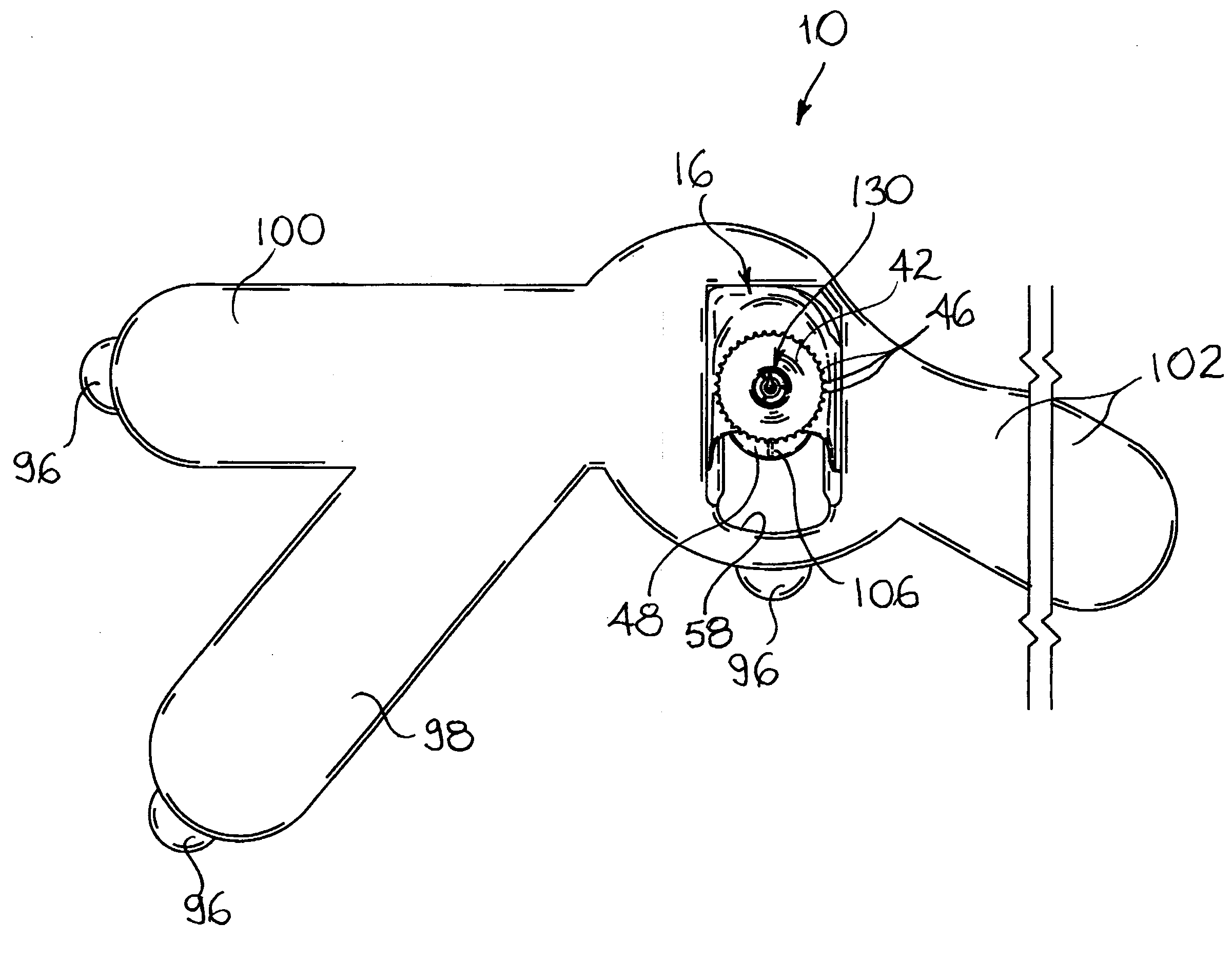
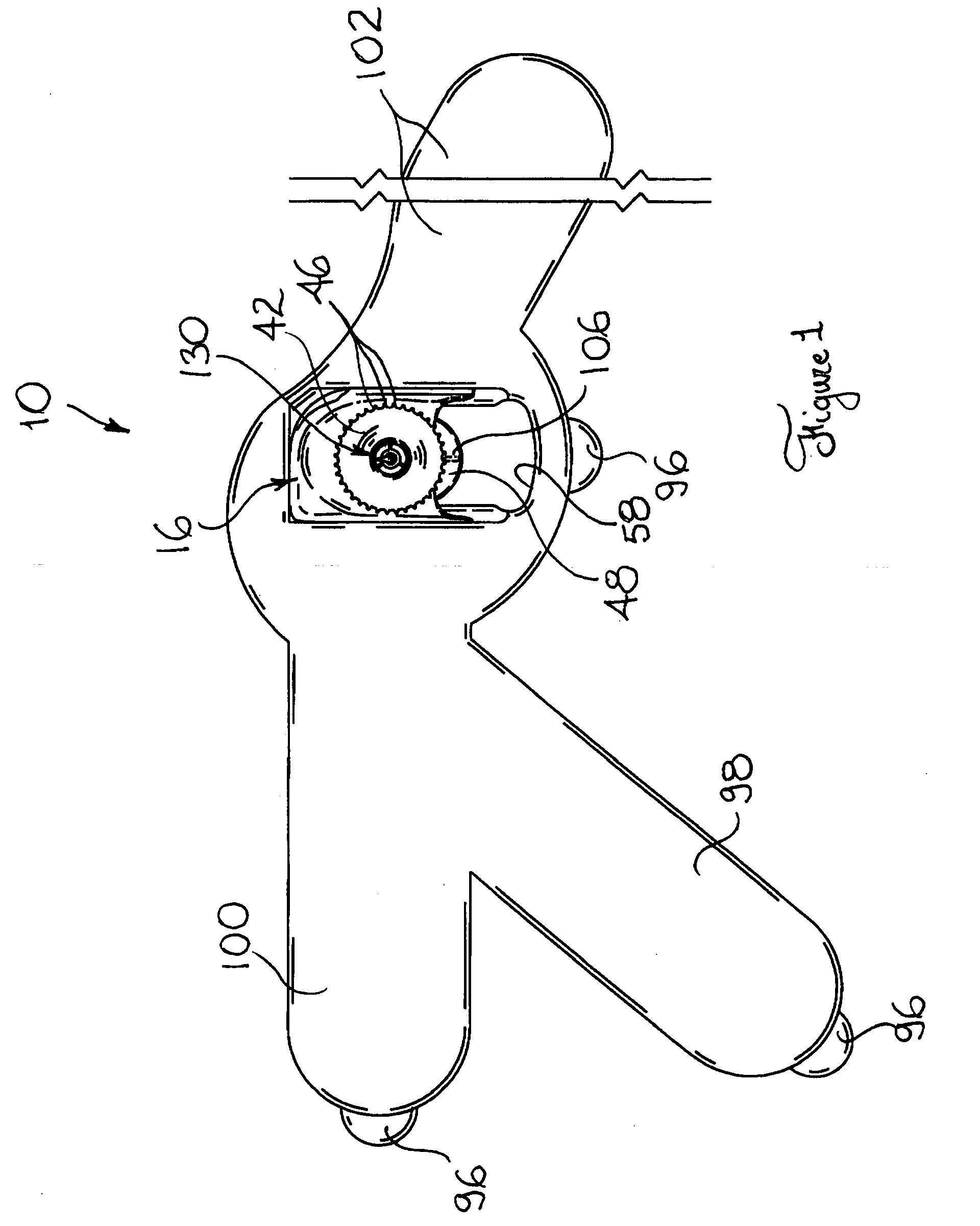
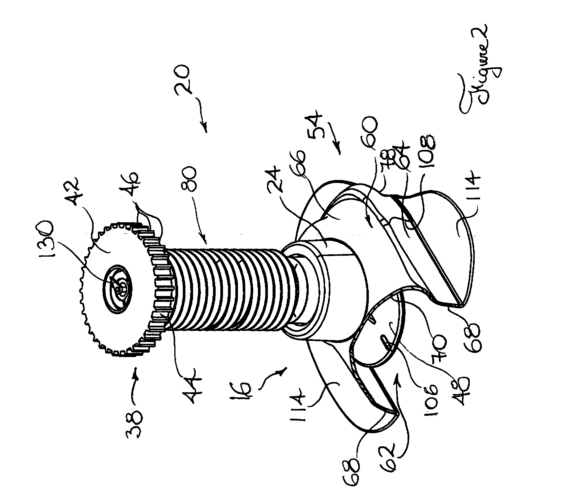
[0084] Referring to FIG. 27, there is shown a styptic device in accordance with an embodiment of the present invention, generally indicated by the reference numeral 10. The styptic device 10 is intended to be used mainly for haemostatically sealing percutaneous vascular punctures. It should, however, be understood that the device 10 could be used in numerous other contexts as a guiding means, and / or pressure creating means, for respectively guiding the insertion of a medical or surgical tool during insertion thereof in a body tissue and / or exerting a predetermined pressure on a body site, without departing from the scope of the present invention.

[0085] Also, the styptic device 10 in accordance with the present invention is hereinafter disclosed mainly for use in the specific context of the cannulation of the femoral artery for the purpose of heart catheterization or coronary angioplasty. It should, however, be understood that the styptic device 10 could be designed for other types ...


PUM


Abstract

A styptic device for hemostatically sealing a percutaneous vascular puncture formed in a body vessel and located at a target anatomical area of an intended patient includes a base component positionable substantially adjacent the target anatomical site. The device also includes a mounting component coupled to the base component for mounting the base component on the intended patient in a substantially adjacent relationship relative to the target anatomical site. The device further includes a compressing component defining a compressing surface for exerting a compressing pressure on the target anatomical site. The compressing component is operatively coupled to the base component so as to be movable relative to the latter between a compressing configuration wherein the compressing surface exerts the compressing force on the target anatomical site and a retracted configuration wherein the compressing surface is spaced from the target anatomical site.

Description

[0001] This application claims the benefit of Provisional Patent Application Ser. No. 60 / 526.918 filed Dec. 5, 2003.FIELD OF THE INVENTION [0002] The present invention relates to the general field of medical devices and is particularly concerned with a device for haemostatically sealing percutaneous vascular punctures. BACKGROUND OF THE INVENTION [0003] There exists a plurality of medical and / or surgical procedures that are carried out intravascularly or intralumenally. For example, in the treatment of vascular diseases, such as atherosclerosis, angioplasty and / or stenting are now widely accepted procedures. [0004] Such procedures usually involve the percutaneous puncture and insertion of a hollow needle through a patient's skin and muscle tissue into the vascular system. A guide wire is then typically passed through the needle lumen into the patient's blood vessel accessed by the needle. The needle may be removed, and an introducer sheath may be advanced over the guide wire into th...

Claims


Application Information

Patent Timeline
Patent Type & Authority Applications(United States)
IPC IPC(8): A61B17/00A61B17/132
CPCA61B17/0057A61B17/1325A61B2017/00659A61B2017/00637A61B2017/00022
Inventor RIOUX, MARCEL
Owner RIOUX MARCEL
Why Eureka
Try Eureka