Electric power shuttling and management system, and method

Inactive Publication Date: 2005-06-09
VILLALOBOS VICTOR M
View PDF13 Cites 189 Cited by
  • Summary
  • Abstract
  • Description
  • Claims
  • Application Information

AI Technical Summary

Benefits of technology

[0028] Accordingly, a feature and advantage of the present invention is its ability to allow advantageous purchase of energy at off-peak rates with storage for subsequent use.

Problems solved by technology

Increasing demands for transmission time have created a bottleneck within the energy transmission industry.
Unfortunately, current channels of transmission continue to get busier and busier, often resulting in the transmission of power approaching gridlock condition during peak usage daylight hours.
As such, the present bottleneck of power transmission has created a business impediment of major proportions for energy re-sellers located in areas where electrical energy is available, but cannot be delivered to the desired end-users, either because the grid is overburdened and stretched to the maximum during the day, or because of too much competition for the same time window.
In 2001, the National Energy Policy reported that the bottleneck of power transmission is one of the most critical energy problems facing the United States today.
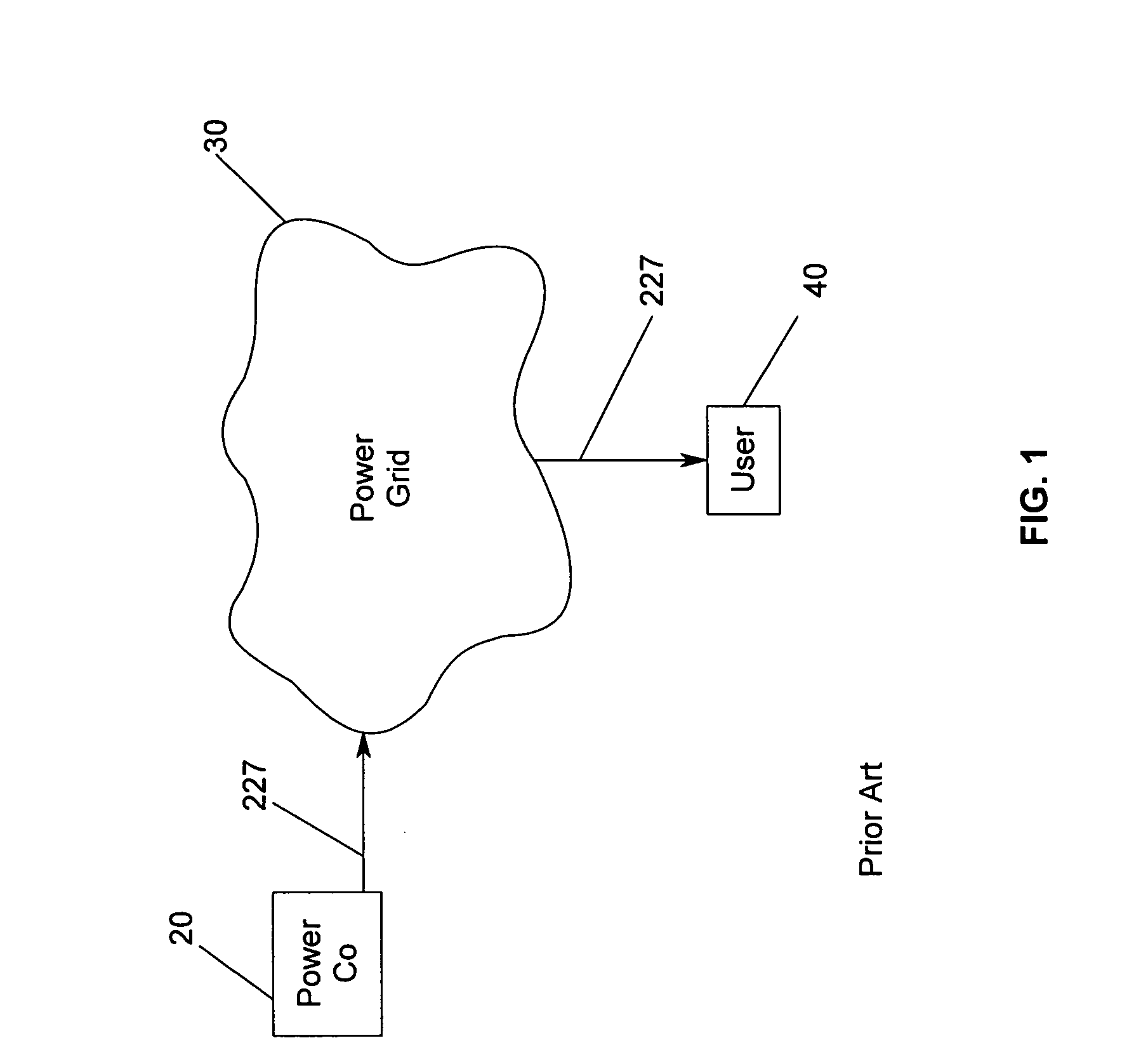
The fact that the national power grid is nearly gridlocked adversely affects all parties involved in the use of electrical energy in America.
That is, the gridlock affects everyone in the United States, from the end user as a homeowner to the commercial building owner, as well as the entire gamut of U.S. industries and companies that require power to regularly conduct business.
However, billions of dollars would be required to effectively reconstruct the grid to allow for more wire capacity, the implementation of which would require a great deal of time.
Although, there are various devices and methods available for generating and / or storing energy and providing the generated and / or stored energy to end-users, such method and device disadvantages that render implementation of same highly inefficient and impractical.
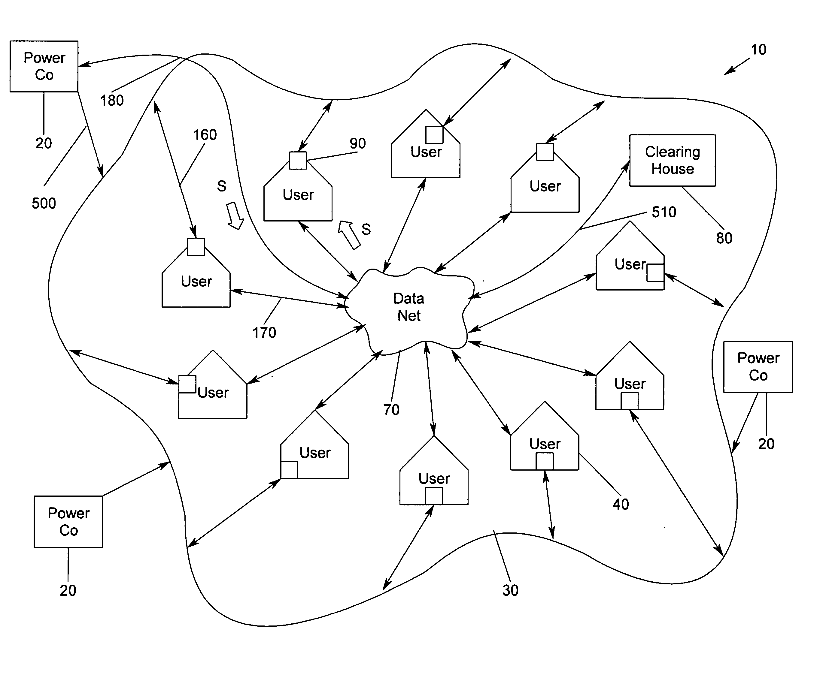
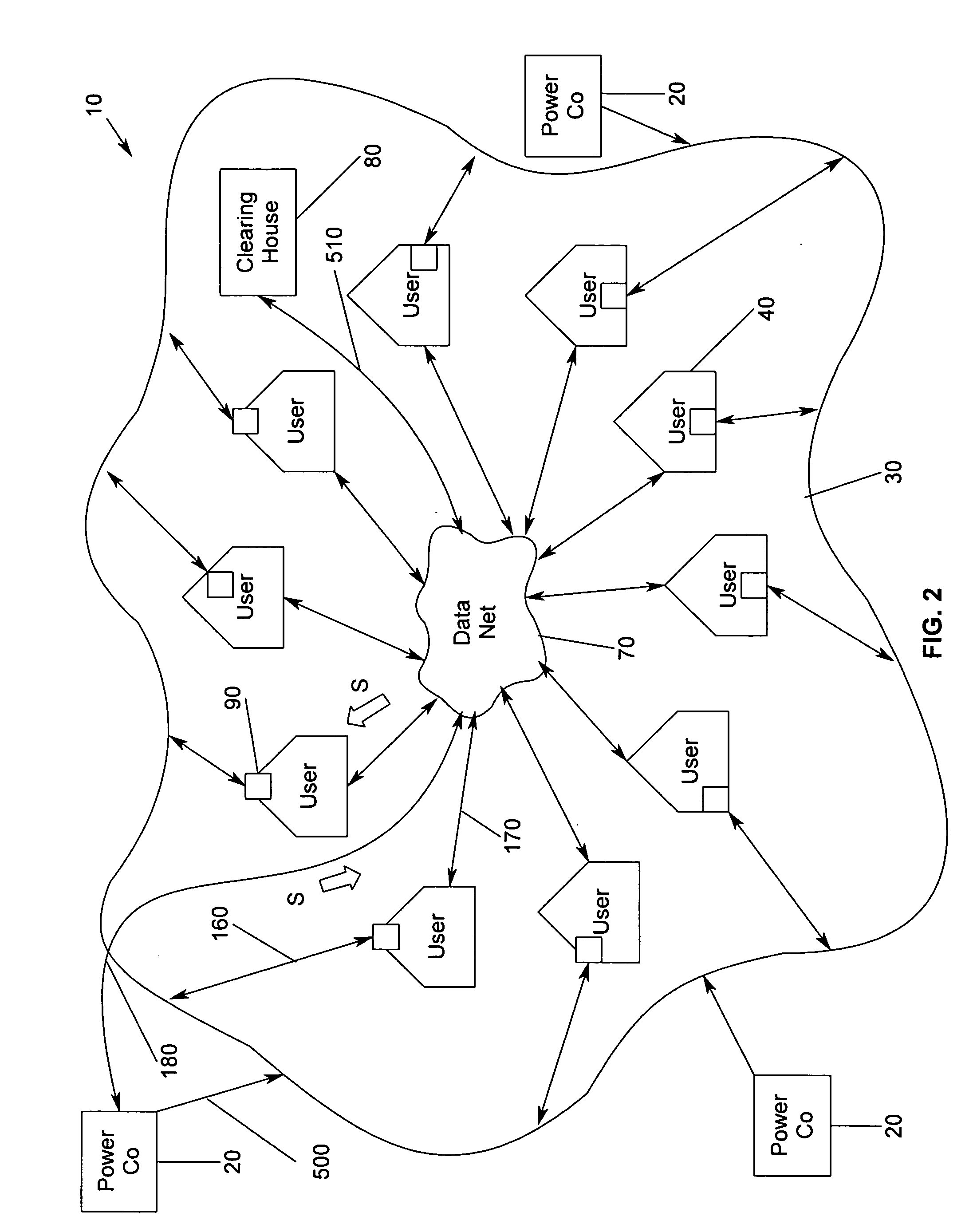
Other devices and methods lack communication and / or coordination between suppliers and users in order to facilitate matching of supply with demand.
Particularly lacking is the aggregation of users and / or suppliers into group sources / users of energy.
Some systems apply to the transmission of power from local grids, but do not address the major problems encountered with intergrid transmission; that is, transmission between local grids over a national grid network via intermediate carriers.
Moreover, such systems do not address the transmission permits required for intergrid use.
Furthermore, such systems would indiscriminately provide energy to the grid, and are, as such, substantially limited in application to the local grid.
Improper scheduling and / or time results in the grid becoming electrically unbalanced.
Further, previous methods and devices do not provide for the trading of energy, or the management of the sale of energy and the cash generated thereby, from the point of sale to the point of delivery and collection of funds.
Current methods deal primarily with storing energy, and do not address the management and / or coordination of energy transmission, nor the collection of funds.
Still other systems fail to address the problem of interstate transmission permitting and coordination, and by default are limited to local energy transmission only.
Additionally, such systems do not provide for the managing of a purchase / sale based on a bid / ask process, nor do they address the collection of cash.
Furthermore, such systems fail to address the purchase of energy from providers in remote locations at an advantageous rate for subsequent sale / use in higher cost locations.
While some or all of the above-referenced devices and methods may well be utilized for storage of energy for subsequent use, each fail to adequately permit the matching of supplies with demands, and further do not facilitate the optimization of energy supply costs via a brokering bid / ask arrangement.

Method used


Image

  • Electric power shuttling and management system, and method
  • Electric power shuttling and management system, and method
  • Electric power shuttling and management system, and method

Examples


Embodiment Construction

[0055] In describing the preferred and selected alternate embodiments of the present invention, as illustrated in the Figures, specific terminology is employed for the sake of clarity. The invention, however, is not intended to be limited to the specific terminology so selected, and it is to be understood that each specific element includes all technical equivalents that operate in a similar manner to accomplish similar functions.

[0056] Referring now to FIG. 1, wherein power flow 227 is depicted, represented therein is the current state of the art, wherein local power company 20 is connected to grid 30. Electricity carried by local power company 20 flows into grid 30 and then flows to user 40, wherein user 40 is a residence, office building, plant facility, or the like. User 40 pays a price rate determined by local power company 20, wherein the rate depends upon the time of day and / or the peak level of power utilized. User 40 is unable to obtain a rate that is advantageous because ...


PUM


Abstract

A method and apparatus for shuttling, managing, and controlling energy flow between suppliers and users based on bid / ask pricing, wherein individual residential / commercial suppliers are aggregated for the purpose of supply and use, and wherein an electricity transmission utility controls the selection and flow of energy from suppliers to users via a controlling device, such as, for exemplary purposes only, a switch turned on by commands sent over a data net to multiple locations simultaneously.

Description

TECHNICAL FIELD [0001] The present invention relates generally to an apparatus and method for coordinating energy sources with users, and controlling the supply of energy between sources and users. More particularly, the present invention relates to a method of brokering energy supplies among various supply sources by aggregating individual supply sources and aggregating users such that energy is economically advantageously obtained via brokering through a bid / ask process. BACKGROUND OF THE INVENTION [0002] It should be noted that energy is the commodity utilized, wherein power is the ability to deliver energy. They are often utilized to describe the same thing, namely, energy and may be utilized interchangeably herein. [0003] Billions of kilowatts of electric energy are transmitted daily across the United States. Increasing demands for transmission time have created a bottleneck within the energy transmission industry. Unfortunately, current channels of transmission continue to get...

Claims


Application Information

Patent Timeline
IPC IPC(8): G06Q30/00
CPCY04S50/10G06Q30/08
Inventor VILLALOBOS, VICTOR M.
Owner VILLALOBOS VICTOR M
Why Eureka
Try Eureka