Adapter for non-circular disc

Inactive Publication Date: 2005-06-09
ORIENT INSTR COMP CO LTD
View PDF1 Cites 4 Cited by
  • Summary
  • Abstract
  • Description
  • Claims
  • Application Information

AI Technical Summary

Benefits of technology

[0012] In this adapter, the non-circular optical disk mounted on the disk receiving section is rotated so that its corners are slipped into below the respective disk press-contact projections, thereby positioning the corners below the respective disk press-contact projections. Following the rotational operation of this disk, at least one of the disk pressing sections and the disk receiving section is gradually forced outside by the corners of the disk, and elastically deformed, and an elastic restoring force is accumulated therein. This accumulated restoring force enables the corners of the disk to be securely sandwiched

Problems solved by technology

The business-card type CD of no regular size is difficult to be installed on an existing disk player without any modification.
This is due to the difficulty in positioning or centering business-card type CDs properly for recording and reproducing within the disk player.
Nevertheless, even the business-card type CD incl

Method used


Image

  • Adapter for non-circular disc
  • Adapter for non-circular disc
  • Adapter for non-circular disc

Examples


first embodiment

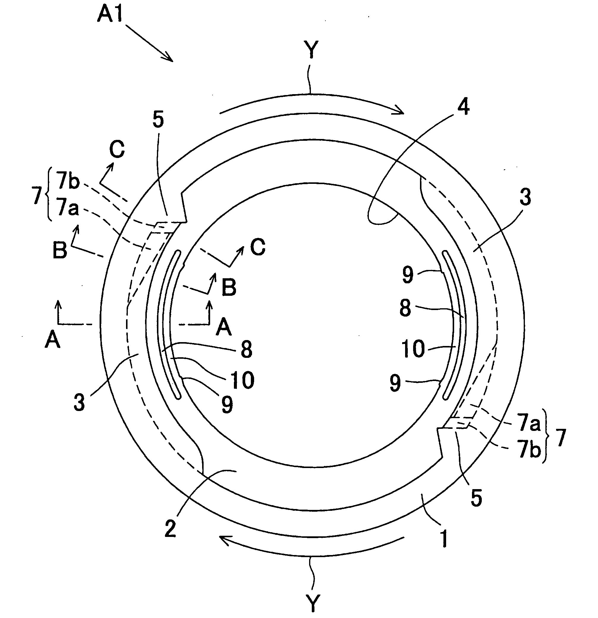
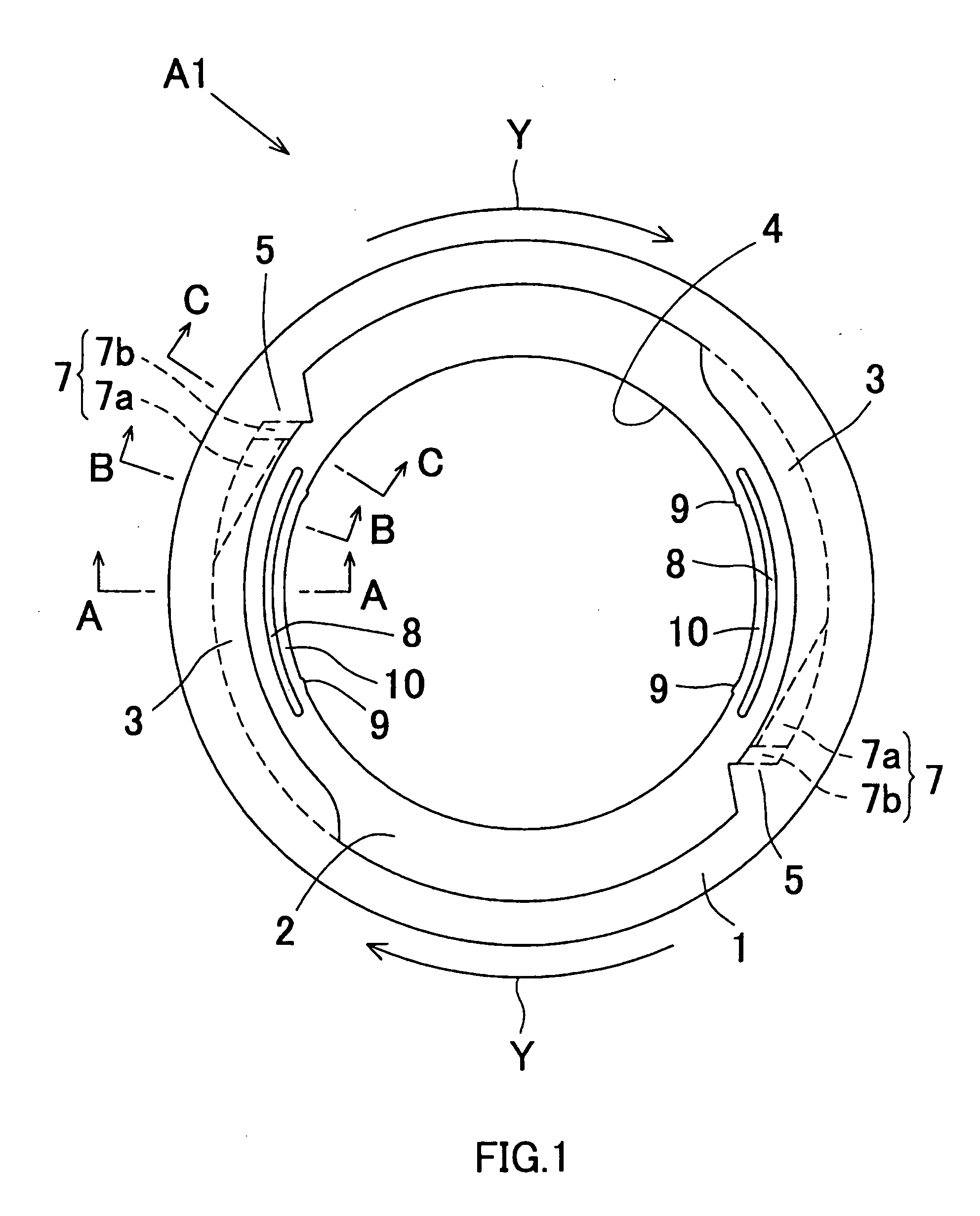
[0052] Referring to FIGS. 1 and 2, reference symbol (A1) denotes a non-circular optical disk adapter according to the present invention. This adapter (A1) is preferably made of an elastic synthetic resin such as ABS or polycarbonate. A business-card type CD (D1) shown in FIGS. 15 and 16 is installed, as a non-circular optical disk, in this adapter (A1). A total weight of the adapter (that is, a sum of a weight of the business-card type CD (D1) and a weight of the adapter (A1)) while this business-card type CD (D1) is installed in the adapter (A1) is set to fall within a range from a weight of a circular optical disk having a diameter of 8 cm to a weight of a circular optical disk having a diameter of 12 cm both of which optical disks are commercially available. In FIG. 1, an arrow (Y) indicates a rotation direction of the business-card type CD (D1) rotated by a spindle (not shown) included in a disk player.

[0053] As shown in FIGS. 15 and 16, this business-card type CD (D1) is a rect...

second embodiment

[0077] A square CD (D3) beside the barrel CD (D2) stated above can be installed, as the non-circular optical disk, in the adapter (A2) as shown in FIG. 20. Since procedures for installing this square CD (D3) are equal to those for installing the barrel CD (D2) stated above, repetitive procedures will not be described herein. In FIG. 20, for convenience of description, the corners (85) of the square CD (D3) are not abutted on the disk abutment sections (5) but arranged to be slightly distant from the disk abutment sections (5).

[0078] The embodiments of the present invention have been described so far. However, the present invention is not limited to the embodiments but settings can be variously changed.

[0079] For instance, according to the embodiments, the disk press-contact projection (7) is composed of the first disk press-contact projection (7a) and the second disk press-contact projection (7b). Alternatively, according to the present invention, the disk press-contact projection...


PUM


Abstract

An adapter A1 made of a synthetic resin includes an annular frame 1 having an outside diameter of 12 cm, a disk receiving section 2 provided continuously on a lower portion of an inner edge of the frame 1, and a pair of disk pressing sections 3 and 3 provided continuously on an upper portion of the inner edge of the frame 1. The disk receiving section 2 is provided with a circular opening 4 for causing an information recording area of a disk to face an optical reader of a disk player. A disk press-contact projection 7 formed so that a projection height is gradually increased in a disk rotation direction Y is provided on a lower surface of each disk pressing section 3. This adapter A1 can securely install a non-circular optical disk even if the optical disk has a slightly different size, and an installation operation of the non-circular optical disk can be easily performed.

Description

TECHNICAL FIELD [0001] The present invention relates to a non-circular optical disk adapter used for adapting a non-circular optical disk like an optical disk, such as a card type CD, a business-card type CD or a DVD, to a disk loader of a disk player included in a computer or the like. [0002] The “disk players” herein include devices which read information recorded on an optical disk, devices which write information to a CD-R, a DVD-R, a DVD-RW, a DVD-RAM, a DVD+R, DVD+RW and the like, and a copying apparatus. BACKGROUND ART [0003] It is known in the art that the standard size of a compact disk (hereinafter, “CD”) on which information is recorded is that of a circle having a diameter of 12 cm or 8 cm. Recently, besides the CD of standard size, a rectangular CD which has a length of about 85 to 89 mm and a width of about 55 to 60 mm, and which includes a central hole and an annular information recording area provided outward of a clamping area has appeared. The CD of this type is re...

Claims


Application Information

Patent Timeline
IPC IPC(8): G11B17/028G11B17/04G11B23/00G11B25/04
CPCG11B17/028G11B17/0408G11B25/046G11B23/0317G11B23/0014
Inventor ITO, TOMOAKIMURATA, MASATOIMAFUKU, MASAKAZU
Owner ORIENT INSTR COMP CO LTD
Why Eureka
Try Eureka