Heat treated high density structures

a high density, heat treatment technology, applied in the direction of snap fasteners, buckles, manufacturing tools, etc., can solve the problems of limiting the individual hook, limiting the strength of the engaging head portion of the hook element, and the density, so as to reduce the thickness of the projection or the hook member, the molecular orientation of the cut portion decreases, and the width of the treated portion generally increases

Inactive Publication Date: 2004-06-17
3M INNOVATIVE PROPERTIES CO
View PDF10 Cites 11 Cited by
  • Summary
  • Abstract
  • Description
  • Claims
  • Application Information

AI Technical Summary

Benefits of technology

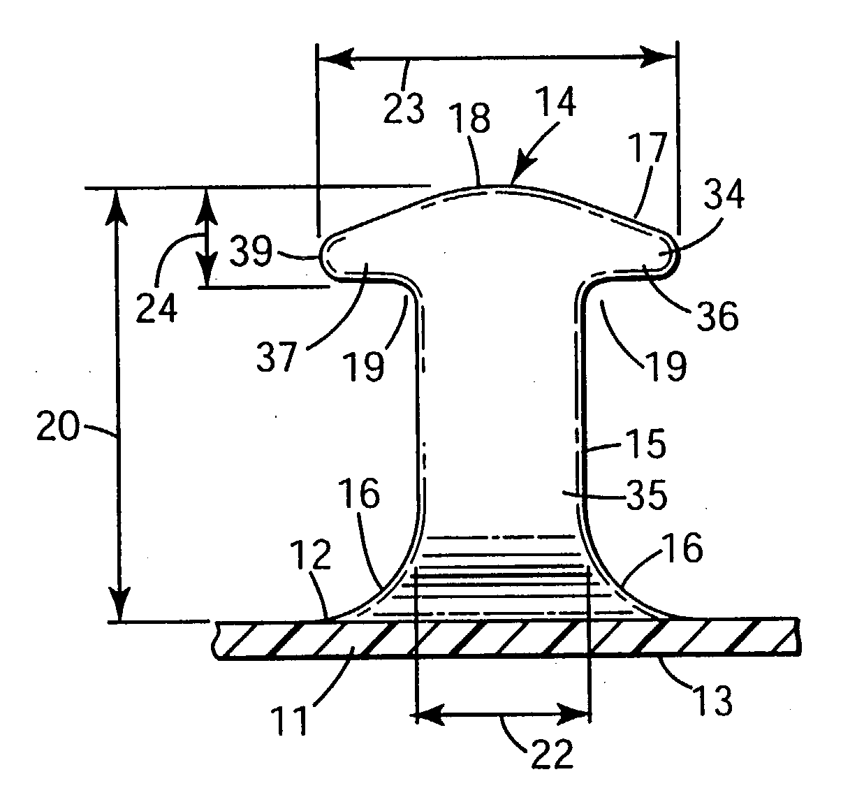
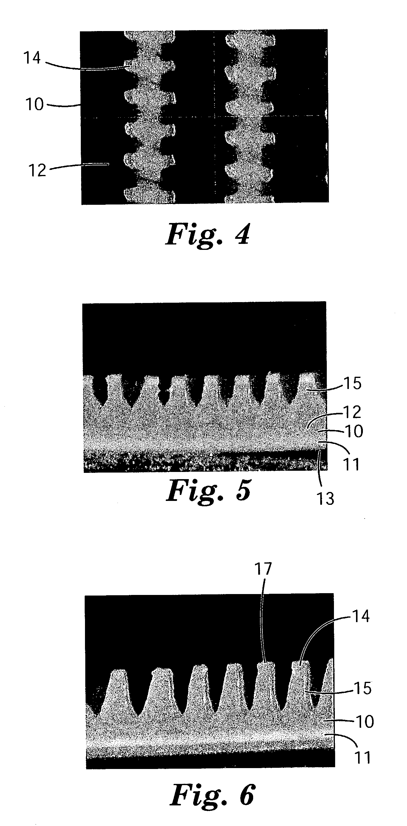
0019] When the cut portions are heat treated in accordance with the invention, the molecular orientation of the cut portions decrease and the resulting projection or hook member thickness dimension decreases. The amount of thickness reduction depends primarily on the amount of cut portion molecular orientation extending in the machine direction or hook thickness dimension. The heat treatment conditions, such as time of treatment, temperature, the nature of the heat source and the like can also effect the cut portion thickness reduction. As the heat treatment progresses, the reduction in cut portion, or projection thickness extends from the top portion, to the base or stem portion down the projection to the base, until the entire cut portion thickness has been reduced. Generally, the thickness reduction is substantially the same in the formed projection as one goes down the projection, when fully heat treated or partially heat treated to the same extent. When only a part of the projection is heat treated, there is a transition zone where the thickness increases from the upper heat treated portion to the substantially non-heat treated portion, which has a substantially unreduced thickness. When the thickness dimension shrinks, the width of the treated portion generally increases, while the overall projection height increases slightly and for a hook the arm droop increases. The end result is a projection or hook member arranged closely spaced in a row where the spacing is one that can either, not be economically produced directly, or cannot be produced at all by conventional methods. The heat treated projection, generally the hook head, and optionally stem, is also characterized by a molecular orientation level of less than 10 percent, preferably less than 5 percent whereas the base film layer orientation is substantially unreduced. Generally, the hook member stem or projection orientation immediately adjacent the base film layer will be 10 percent or higher, preferably 20 percent or higher.
0020] The heat treatment is generally carried out at a temperature near or above the polymer melt temperature. As the heat gets significantly above the polymer melt temperature, the treatment time decreases so as to minimize any actual melting of the polymer in the hook head portion or top of the projection. The heat treatment is carried out at a time sufficient to result in reduction of the thickness of the hook head, and / or stem, but not such that there is a significant deformation of the base layer or melt flow of the hook head portion or top of the projection. Heat treatment can also result in rounding of the hook head portion edges, improving tactile feel for use in garment applications.
0021] The invention projections can be arranged in very close proximity, for example, if closely spaced hooks or projections are desired, there can be 25 / cm or more hooks or projections in a single row. A row is defined by hooks or projections that extend in a direction or extent and at least partially overlap in that direction or extent, preferably overlap by 50 percent or more most preferably 90 percent or more. Preferably, the hooks or projections can be at least 30 / cm even 50 / cm or more up to 100 / cm or possibly more. The overall density of the projections or hook members can be extremely high based on the closeness and width of the original rib members. If the rib members are closely spaced, extremely high hook densities are possible. Wider spacing between rib members can be created after the ribs are formed by stretch orientation of the base in a direction transverse to the rib members or hook rows. This can be beneficial to reduce the base layer thickness and made it more softer or less rigid while maintaining high number of projections in a row.

Problems solved by technology

This generally inherently limits the individual hooks to those capable of engaging only in a single direction while also limiting the strength of the engaging head portion of the hook element, as well as the density of the hook structures, which generally must point in the machine direction.
However, this approach is not commercially viable due to the speed of the milling operation.

Method used


Image

  • Heat treated high density structures
  • Heat treated high density structures
  • Heat treated high density structures

Examples


example 1

[0044] The precursor hook web described above was subjected to a non-contact heat treatment on the hook side of the web by passing said web underneath a perforated metal plate at a speed of 2.4 meter / min producing hook members having a profile substantially as shown in FIG. 7. Hot air at a temperature of approximately 185.degree. C., provided by a 15 kW electric heater, was blown through the perforations in the metal plate onto the hook side of the web at a velocity of approximately 3350 meter / min. The hooks were approximately 46 cm from the perforated plate. The smooth base film side of the web was supported on a chill roll at approximately 149.degree. C. After heat treatment the web was cooled by passing the web over a chill roll maintained at 11.degree. C. The dimensions of the resulting heat-treated hook material are shown in Table 1 below.

example 2

[0045] The precursor hook web described above was subjected to a non-contact heat treatment on the hook side of the web using the following procedure. A 13 cm.times.43 cm piece of web was placed onto a 13 cm.times.43 cm steel plate (1.3 cm thick), hook-side up, and edge clamped to prevent the web from shrinking. Hot air from a Master brand hot air gun (14.5 amp) at 400.degree. C. was blown vertically down onto the web by passing the air gun uniformly over the web for about 20 seconds. The hot air gun vent was set at 50%. The dimensions of the resulting heat-treated hook material are shown in Table 1 below.

1TABLE 1 Hook Hooks / cm Hook Hook Arm Hook Thickness in a row in Hook width Height Droop Thickness at 300 .mu.m Machine Material (.mu.m) (.mu.m) (.mu.m) Top (.mu.m) (.mu.m) Direction Precursor 384 521 74 349 324 30 C1 374 494 69 319 324 8 1 508 594 130 124 203 30 2 553 616 156 120 164 30


PUM

PropertyMeasurementUnit
angleaaaaaaaaaa
shrinkageaaaaaaaaaa
thicknessaaaaaaaaaa

Abstract

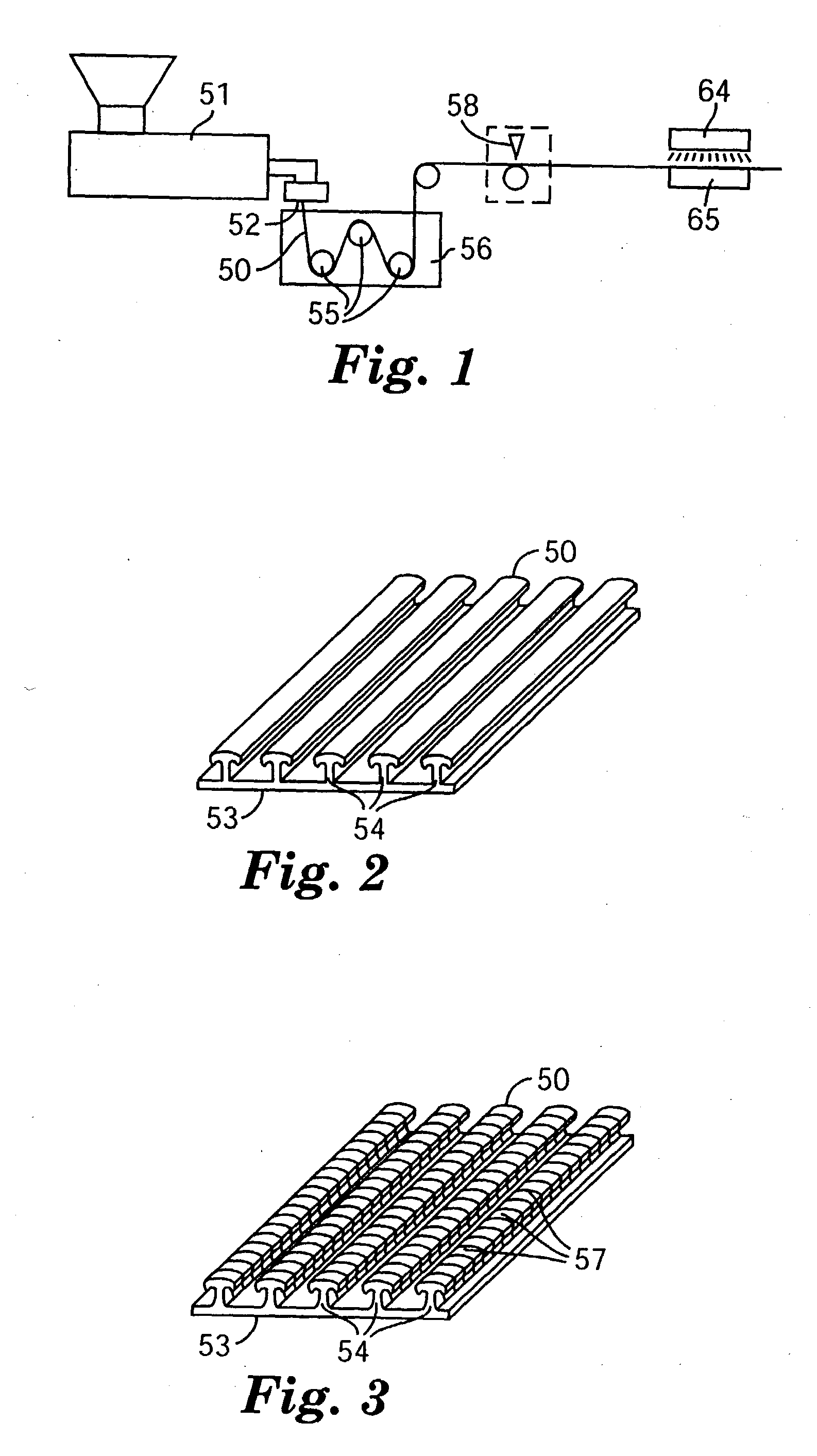
A method for forming a unitary polymeric projection or fastener comprising a base layer, and a multiplicity of spaced projections or hook members projecting from the upper surface of the unitary base layer the method generally including extruding of forming a thermoplastic resin through a die plate or mold. A die plate, if used, is shaped to form a base layer and spaced ridges, projecting above a surface of the base layer. When the die forms the spaced ridges or ribs the cross sectional shape of the projections are formed by the die plate. The ridges are then cut at spaced locations along their lengths to form discrete cut portions of the ridges. The cut portions are then heat treated resulting in shrinkage of at least a portion of at least the cut portion thickness by from 5 to 90 percent, preferably 30 to 90 percent thereby forming discrete upstanding projections.

Description

BACKGROUND AND SUMMARY[0001] The present invention concerns molded hook fasteners for use with hook and loop fasteners.[0002] There are a variety of methods known to form hook materials for hook and loop fasteners. One solution is generally the use of continuous extrusion methods that simultaneously form the base layer and the hook elements, or precursors to the hook elements. With direct extrusion molding formation of the hook elements, see for example U.S. Pat. No. 5,315,740, the hook elements must continuously taper from the base layer to the hook tip to allow the hook elements to be pulled from the molding surface. This generally inherently limits the individual hooks to those capable of engaging only in a single direction while also limiting the strength of the engaging head portion of the hook element, as well as the density of the hook structures, which generally must point in the machine direction.[0003] An alternative direct molding process is proposed, for example, in U.S....

Claims


Application Information

Patent Timeline
Patent Type & Authority Applications(United States)
IPC IPC(8): A44B18/00
CPCY10T24/2792A44B18/0065A44B18/00
Inventor AUSEN, RONALD W.SETH, JAYSHREE
Owner 3M INNOVATIVE PROPERTIES CO
Why Eureka
Try Eureka