Thermoelectric heat pump with direct cold sink support

a heat pump and sink technology, applied in the field of thermoelectric heat pumps, can solve the problems of reducing thermal efficiency, reducing thermal efficiency, and costly substrates, and achieve the effects of reducing expensive and thermally inefficient, effective sealing against moisture and moisture vapor, and reducing cos

Inactive Publication Date: 2005-06-16
THERMOELECTRIC DESIGN
View PDF21 Cites 109 Cited by
  • Summary
  • Abstract
  • Description
  • Claims
  • Application Information

AI Technical Summary

Benefits of technology

[0017] The present invention is a TE module assembly that eliminates expensive and thermally inefficient electrically-insulating substrates, is inexpensively and effectively sealed against moisture a

Problems solved by technology

One disadvantage is the use of the insulating substrates 14 and 16, typically alumina ceramic.
The substrates are costly and reduce thermal efficiency by adding resistance to the flow of heat; this resistance to heat flow is called thermal resistance.
The disadvantages to this design are that it does not lend itself to moisture sealing, has poor structural support for the huge hot sinks, and relies on flexible electrical connections between the spaced cold sink plates in each TE pair to protect the TE elements from thermal stresses.
Lindenblad's assembly also appears to rely on an inadequate natural, fanless convection to remove heat from the interconnected hot sinks, possibly due to a widely held belief at the time that the efficiency of the TE materials would improve by orders of magnitude, which large improvement never occurred.
One problem with this approach is that the aluminum has three to four times the thermal expansion of alumina ceramic and causes stress fractures of the solder bonds that connect the TE elements to the copper connectors upon heating and cooling.
Although used successfully in large-scale applications such as the cooling of trains and submarines, this technique is prohibitively expensive and complex in small-scale applications, particularly in consumer products.
This basic structure is believed to be relatively fragile and difficult to ship and handle for assembly.
While Yamada et al. focuses on liquid-cooled arrangements, the less-detailed air-cooled embodiments replace the T-shaped electrodes with conventional flat electrodes bonded directly to a conventional unitary hot sink with a conventional insulating layer, similar to the Haba structure described above and believed to have similar s

Method used


Image

  • Thermoelectric heat pump with direct cold sink support
  • Thermoelectric heat pump with direct cold sink support
  • Thermoelectric heat pump with direct cold sink support

Examples


Embodiment Construction

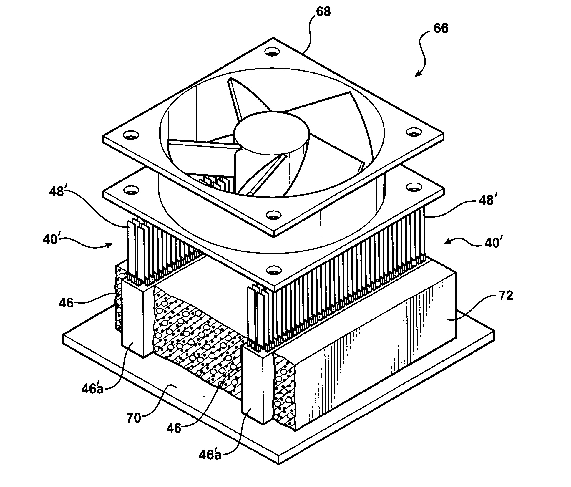
[0037]FIGS. 3, 3A, and 3B show a preferred basic embodiment of the invention, illustrated as an integrated thermoelectric (TE) assembly or module 40. The typical alumina substrates have been eliminated. An array of N and P thermoelectric semiconductor elements 42a and 42b of conventional type has their heat-absorbing or “cold side” ends (the lower ends of the elements in FIGS. 3 and 3A) connected by flat copper connector tabs 44. The connector tabs 44, however, are bonded directly to a rigid, unitary cold sink 46, in the illustrated embodiment a one-piece extruded block of aluminum cut and anodized, with a thick spacer portion 46a and a plurality of heat exchanging fins 46b. Spacer portion 46a has a mounting / support surface 46c with an area preferably greater than the area 46d (FIG. 3B, broken lines) bounding the array of P / N elements 42a and 42b. Cold-side connectors 44 are preferably attached to cold sink 46 with a thermally conductive adhesive (not shown) in known manner, and to ...


PUM


Abstract

A thermoelectric heat pump module of the type used in small cooling applications and appliances, such as a thermoelectric picnic cooler. The module comprises an array of thermoelectric elements with cold-side connectors directly bonded to a large, unitary cold sink for support, and hot-side connectors each having an integrated heat exchange fin to form a small, lightweight, but efficient hot sink array directly bonded to the elements without thermal stress. The cold sink is larger than the hot sink array. The cold-side connectors and at least portions of the thermoelectric elements are sealed and supported with a layer of potting material built up from the surface of the cold sink, and optionally insulated with an additional layer of sealed foam, eliminating moisture vapor transmission, condensation, and corrosion in the module. In a preferred form, the elements and their finned hot-side connectors are arranged in an elongated, narrow-depth array designed to be placed perpendicular to a flow of cooling air, and allowing multiple modules to be used in a distributed pattern with a single air-mover such as a fan.

Description

FIELD OF THE INVENTION [0001] The present invention is in the field of thermoelectric (TE) heat pumps of the type used in smaller scale cooling and heating appliances. BACKGROUND OF THE INVENTION [0002] TE heat pumps are well known and offer an efficient means for pumping or moving small amounts of heat, generally less than 200 watts. Well known uses include temperature controlling (cooling or heating) small enclosures that contain such items as food, wine, medicine or electronics, and direct temperature control of electronic chips and laser diode devices by direct placement of a TE heat pump on a device. A less well-known application for TE technology is to pump heat through the TE unit to produce electrical power, known as a TE generator. [0003] A conventional TE device, chip, or module 20 is shown in FIG. 1 with the typical upper alumina substrate 14 removed. The module consists of an array of negatively (N) and positively (P) doped thermoelectric semiconductor elements, 10a and ...

Claims


Application Information

Patent Timeline
IPC IPC(8): F25B21/02H01L35/30H01L35/32
CPCF25B21/02H01L35/32H01L35/30F25B2321/0251H10N10/13H10N10/17
Inventor CAUCHY, MATT J.
Owner THERMOELECTRIC DESIGN
Why Eureka
Try Eureka