Potting method for membrane module

Inactive Publication Date: 2005-06-16
ZENON TECH PARTNERSHIP
View PDF10 Cites 16 Cited by
  • Summary
  • Abstract
  • Description
  • Claims
  • Application Information

AI Technical Summary

Benefits of technology

[0009] According to another aspect of the invention, a fugitive potting method uses two layers of fugitive materials. A first fugitive layer is provided adjacent the surface, for example the top or bottom surface, of a header shell. A second fugitive layer is provided adjacent the first layer. The first layer resists penetration of the fibers more than the second layer. The membranes are inserted into the second layer and may pass partially or completely through it. However, when the ends of the membranes reach the first layer, resistance to further penetration increases and the membranes are not inserted all the way thro

Problems solved by technology

This migration and leveling off of the resin generally takes a considerable amount of time.
Also, uneven initial application of the resin (along the edges of the bundles) can disturb the underlying fugitive material and result in uneven

Method used


Image

  • Potting method for membrane module
  • Potting method for membrane module
  • Potting method for membrane module

Examples


Embodiment Construction

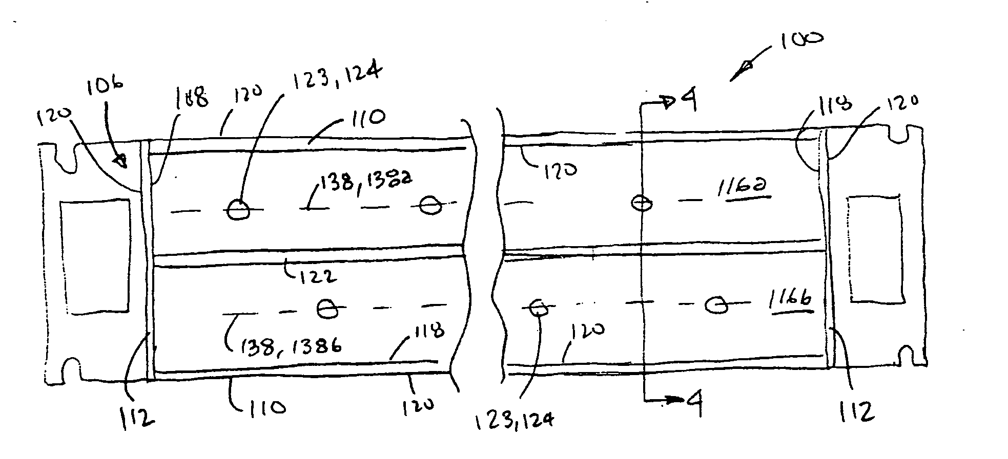
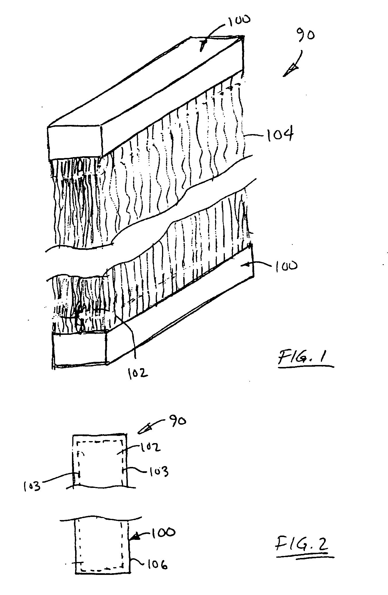
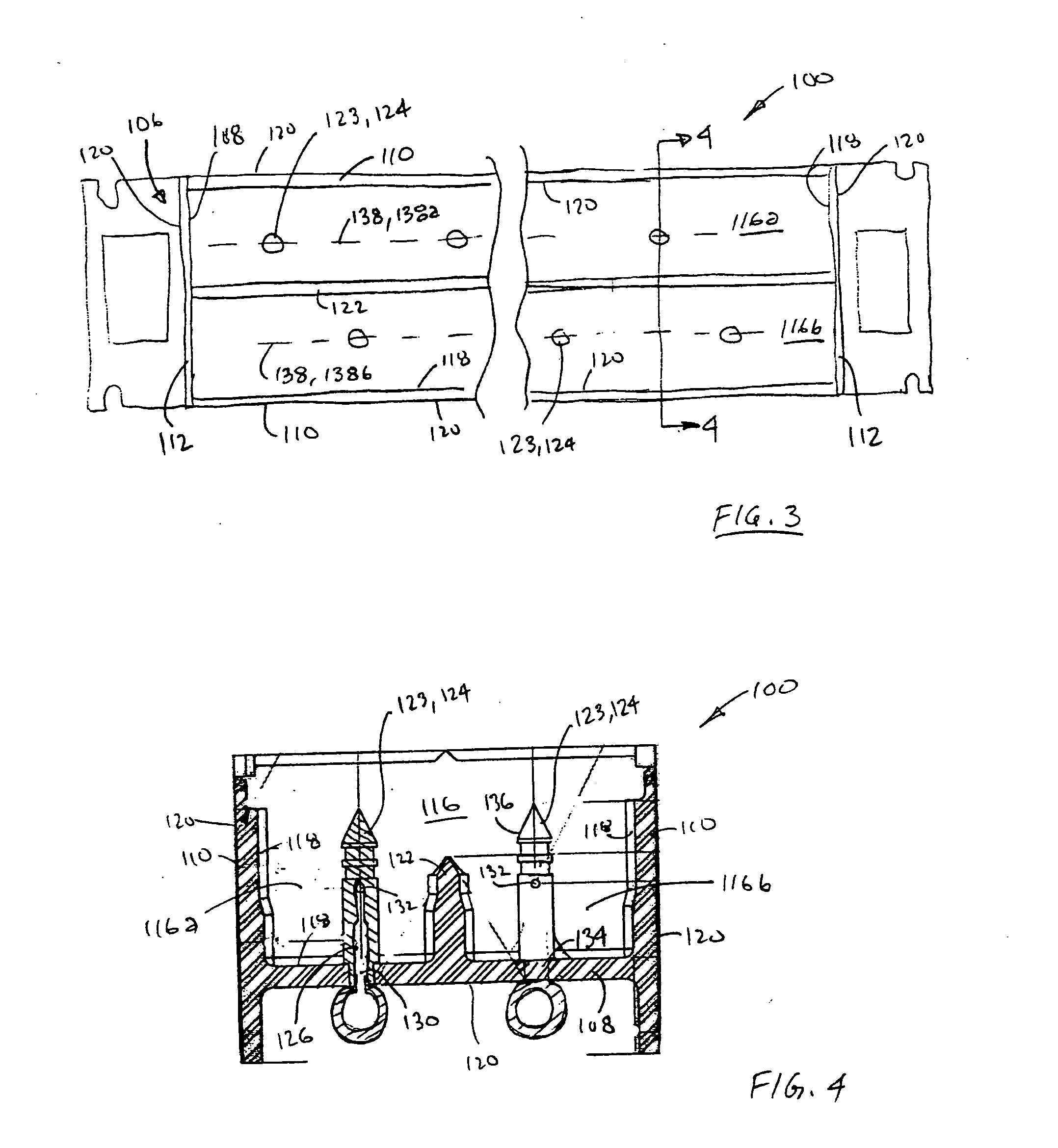
[0021] A filtration module 90 having a header potted according to the present invention is shown generally in FIG. 1. The module 90 has opposed headers 100 and a bundle 102 of permeating hollow fiber membranes 104 extending between the headers 100. The bundle 102 is configured in an elongate rectangular shape when viewed from above (FIG. 2), having a generally rectangular perimeter 103 (shown in phantom line) in a plane perpendicular to the axis of the hollow fiber membranes. Other configurations, such as, for example but without limitation, modules with a single header at one end of a bundle, modules with tow or more bundles of fibers, and headers / bundles with circular perimeters, or perimeters of other shapes, can also be provided within the scope of the present invention.

[0022] Referring now to FIGS. 3 and 4, each header 100 has a shell 106 that can be generally channel shaped and rectangular in cross-section. Each shell 106 has a base 108, and sidewalls 110 and end walls 112 th...


PUM

PropertyMeasurementUnit
Electrical resistanceaaaaaaaaaa
Widthaaaaaaaaaa
Areaaaaaaaaaaa

Abstract

A membrane module is made by inserting ends of membranes into a container and injecting resin directly into a space between adjacent membranes. The container may be a header shell having ducts for injecting the resin from outside of the header to the space between the adjacent membranes. The ducts may pass through a part of the header which forms a permeate cavity. The permeate cavity may be filled with a fugitive material while the resin is being injected.

Description

[0001] This is an application claiming the benefit under 35 USC 119(e) of U.S. Provisional Application Ser. No. 60 / 531,995, filed Dec. 24, 2003. All of U.S. Ser. No. 60 / 531,995 is incorporated herein by this reference to it.FIELD OF THE INVENTION [0002] This invention relates to membrane modules for water treatment and, more particularly, to potting membranes into a header. BACKGROUND OF THE INVENTION [0003] Membranes can be used in water treatment units to extract permeate from a supply of water. Immersed membranes may be used for extracting clean water (permeate) from a tank of contaminated water containing solids or mixed liquor. The membranes may be potted in headers, and can be assembled in modules, each module having many membranes extending from a header. A source of suction can be provided to the headers to withdraw permeate through the membrane walls and into the lumens of the fibers. The permeate can then be drawn into a permeate collection cavity in or adjacent to the hea...

Claims


Application Information

Patent Timeline
IPC IPC(8): B01D63/00B01D63/02
CPCB01D63/022B01D63/02
Inventor COTE, PIERRE LUCIENYACOUB, FRANCOISPEDERSEN, STEVEN KRISTIAN
Owner ZENON TECH PARTNERSHIP
Why Eureka
Try Eureka