Ladle bottom

a technology of ladle bottom and slag, which is applied in the field of refractory articles, can solve the problems of molten metal and slag to mix, difficulty in casting or refining operations, and defects in intermediate or final metal products, so as to reduce the amount of discarded metal, avoid the premature flow of slag, and increase the efficiency of ladle draining operation

Inactive Publication Date: 2005-06-16
VESUVIUS USA CORP
View PDF3 Cites 21 Cited by
  • Summary
  • Abstract
  • Description
  • Claims
  • Application Information

AI Technical Summary

Benefits of technology

[0009] An object of the present invention is to increase the efficiency of a ladle draining operation, including reducing the amount of...

Problems solved by technology

Contamination is undesirable and may cause difficulties in casting or refining operations as well as defects in the intermediate or final metal products.
Slag contamination can occur from both floating and entrained slag.
Entrainment often occurs when turbulence disturbs the interface between molten metal and slag.
Such turbulence can cause molten metal and slag to mix.
Under quiescent conditions, entrained slag would eventually float to the surface; however, the turbulence of casting can maintain a substantial amount of entrained slag in the molten metal.
As the metal drains from the ladle, the floating slag ap...

Method used


Image

  • Ladle bottom
  • Ladle bottom
  • Ladle bottom

Examples


Embodiment Construction

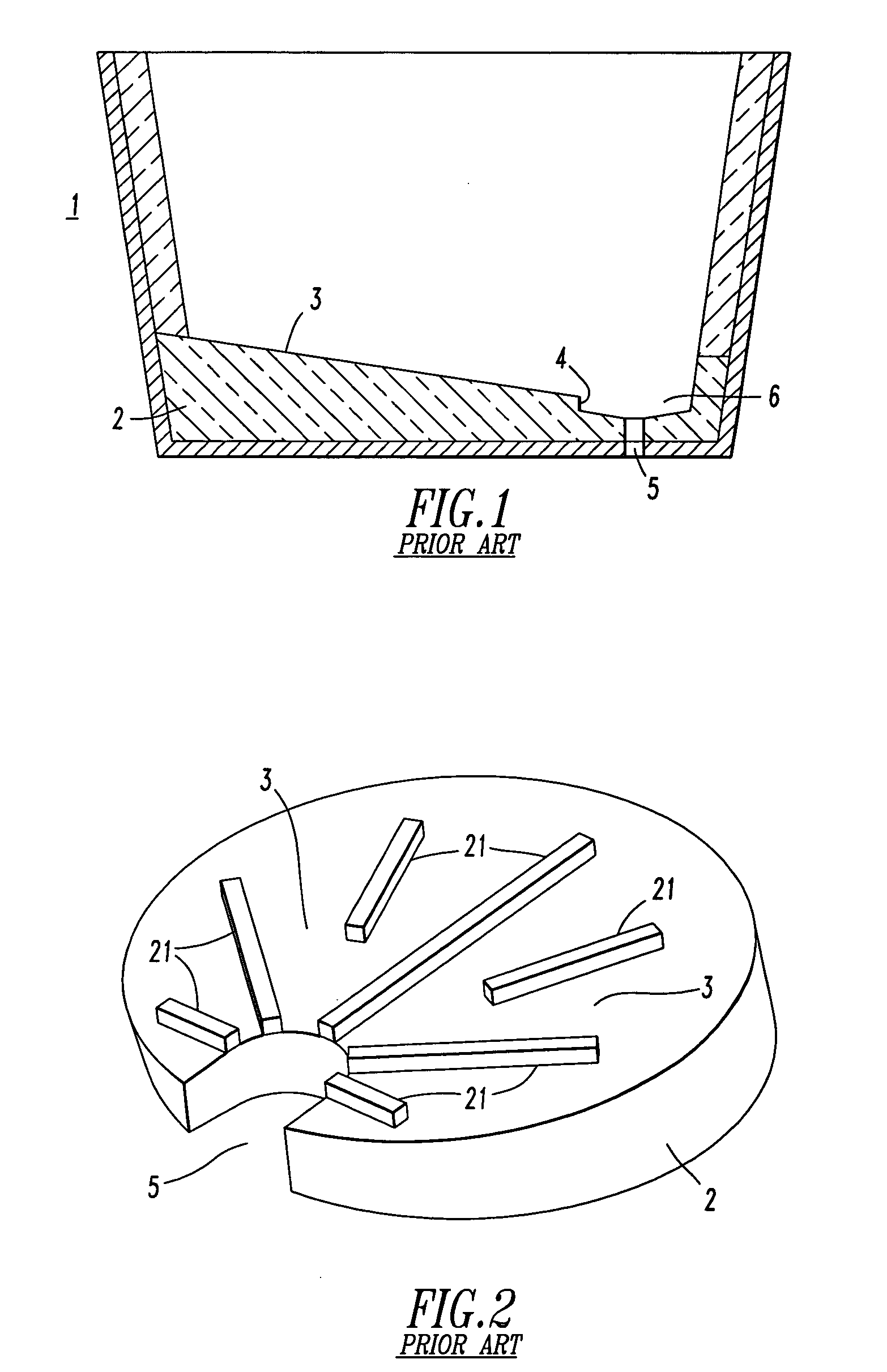
[0017]FIG. 1 shows a ladle 1 of the prior art having a bottom 2. The bottom 2 comprises an inclined portion 3 and a vertical portion 4 adapted to direct molten metal in the ladle 1 to an outlet 5. The vertical portion 4 creates a well 6 immediately above the outlet 5. Molten metal is directed to the outlet 5 by the inclined portion 3, and collects in the well 6 before any slag, which may be floating on the molten metal. The well 6 is described as increasing the amount of molten metal that can pass through the outlet 5 before floating slag contaminates the outflow.

[0018]FIG. 2 shows another ladle bottom 2 of the prior art having an inclined surface 3 directed toward the outlet 5. Molten metal, being heavier than slag, is expected to reach the outlet 5 before any floating slag. A plurality of castellations 21 rises from the inclined surface 3. The castellations are described as reducing vortexing, thereby decreasing the likelihood slag will entrain in the molten metal. Less entrained...


PUM

PropertyMeasurementUnit
Flow rateaaaaaaaaaa
Heightaaaaaaaaaa

Abstract

The present invention relates to a metallurgical ladle and more particularly to the bottom of the ladle having an outlet through which the molten metal can drain. An object of the present invention is to increase the efficiency of a ladle draining operation, including reducing the amount of discarded metal, avoiding the premature flow of slag through the outlet, and reducing the contamination of slag in the molten metal effluent. The ladle bottom comprises a plurality of terraces and flow channels, ultimately directing the stream of molten metal to an outlet of the ladle. The terraces are described as capturing slag and the channels permit molten metal to flow preferentially through the outlet.

Description

FIELD OF THE INVENTION [0001] This invention relates generally to refractory article and, more particularly, to a refractory shape used in the transfer of molten metal in a continuous casting operation. BACKGROUND [0002] A ladle is a vessel that is used to hold or transport a batch of liquid metal during metallurgical operations. A layer of slag frequently covers the top surface of the liquid metal, such as in the production of steel. When desired, the liquid metal may be drained from the ladle though an outlet located in the ladle bottom. While draining, the metal will, desirably and advantageously, completely empty from the ladle without contamination of the metal by slag. Contamination is undesirable and may cause difficulties in casting or refining operations as well as defects in the intermediate or final metal products. [0003] Slag contamination can occur from both floating and entrained slag. Slag is typically less dense than liquid metal and generally floats in a separated l...

Claims


Application Information

Patent Timeline
IPC IPC(8): B22D41/08B22D41/50B22D43/00
CPCB22D43/001B22D41/08Y02P10/20B22D43/00
Inventor RICHAUD, JOHANHEASLIP, LAWRENCE J.DORRICOTT, JAMES D.
Owner VESUVIUS USA CORP
Why Eureka
Try Eureka