Position indicator and position detector

a position indicator and detector technology, applied in the direction of instruments, ac/dc measuring bridges, code conversion, etc., can solve the problems of increasing power consumption, reducing detection frequency (reading speed), and increasing product cost, so as to achieve short time and high resolution

Active Publication Date: 2005-06-16
WACOM CO LTD
View PDF6 Cites 22 Cited by
  • Summary
  • Abstract
  • Description
  • Claims
  • Application Information

AI Technical Summary

Benefits of technology

[0016] As described above, according to the present invention, the detection of operation information represented as a continuous quantity can be performed in a short time and with high resolution.

Problems solved by technology

However, enhancing the frequency of the alternating current signals requires expensive circuit elements, which causes a rise in the product cost and incurs an increase in power consumption.
On the other hand, elongation of the length of time has a problem of causing a reduction in the detection frequency (reading speed) with respect to operational information or positional information including a continuous quantity.

Method used


Image

  • Position indicator and position detector
  • Position indicator and position detector
  • Position indicator and position detector

Examples


first embodiment

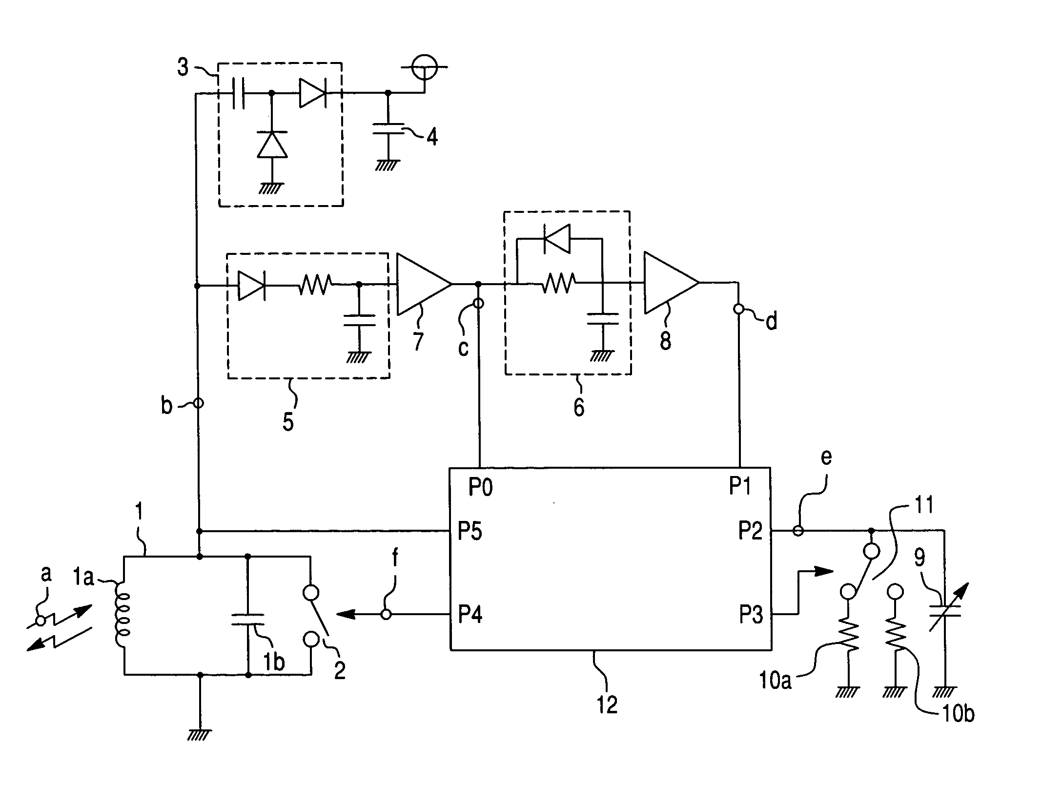
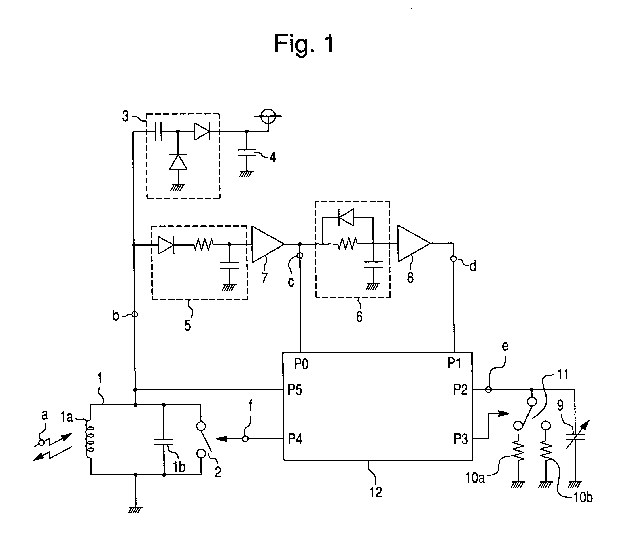
[0026]FIG. 1 shows a position indicator according to the present invention. In FIG. 1, reference numeral 1 denotes a resonant circuit; 2 a switch; 3 a power source extraction circuit; 4 a capacitor for a power source; 5 a detector circuit; 6 an integration circuit; 7 and 8 denote buffers; 9 denotes a variable capacitor; 10a and 10b are resistors; 11 denotes a changeover switch; and 12 is a microcomputer.

[0027] The resonant circuit 1 comprises a coil 1a and capacitor 1b, and has a resonant frequency substantially the same as the frequency f0 of electromagnetic waves transmitted from a tablet (not shown). The switch 2 is on / off controlled by the microcomputer 12, and changes the characteristic of the resonant circuit 1 by changing over the opposite terminals of the capacitor 1b to open or short circuit conditions. Here, the switch 2 changes the signal to be transmitted to the tablet side by changing over the resonant circuit 1 to an acting condition or a non-acting condition, that is,...

second embodiment

[0072] In the above-described second embodiment, the processing of STEPs 35, 40, and 45 constitutes discharging / charging means, the processing of STEPs 42 to 44 constitutes counting means, the processing of STEPs 34 to 48 constitutes time-constant setting means, and the processing of STEPs 33 and 47 constitutes calculating means.

[0073] In the above-described embodiment, the number of combined resistors and switches to be connected to the input / output terminals of the microcomputer may be increased to perform detection with high resolution. Also, the counter in the microcomputer may be a type that counts clock signals from the microcomputer.

[0074] Tablets to be used in the first and second embodiments may include those that detect information, such as an operation, as a signal level on the basis of the presence / absence of a signal from the position indicator. For example, as such, there are arrangements that are disclosed in the first embodiment in Japanese Unexamined Patent Applica...


PUM


Abstract

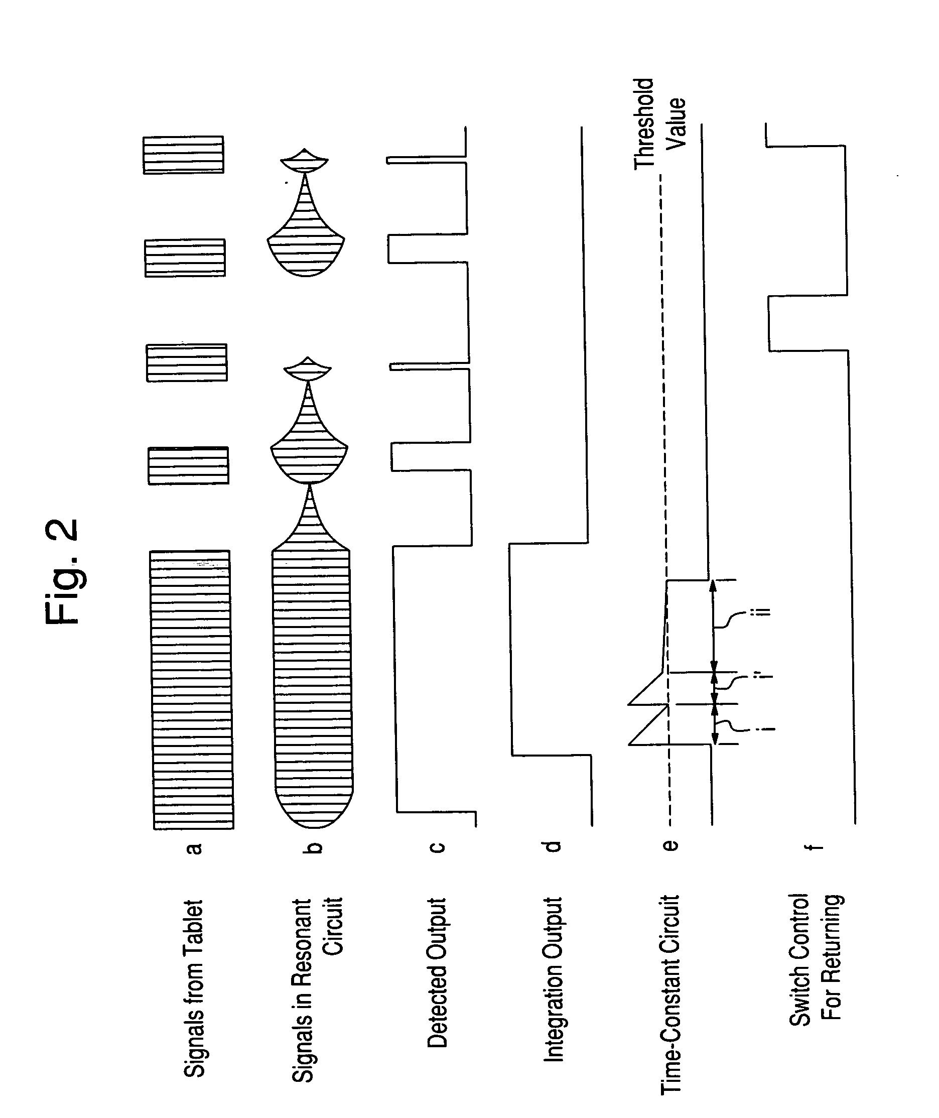
A position indicator includes a time-constant circuit having an element whose characteristic continuously varies in response to operation represented as a continuous quantity such as writing force, and capable of switching the variation range of time constant in response to the variation in characteristic of the element in at least two ways; and a discharging/charging device capable of discharging the time-constant circuit from a predetermined voltage to a voltage below a specified voltage, or charging the time-constant circuit from the predetermined voltage to a voltage exceeding the specified voltage. Using the time-constant circuit and discharging/charging device, the number of waves of AC signals at a specified frequency is counted from the discharge start time to the time when the voltage falls below the specified voltage, or from the charge start time to the time when the voltage exceeds the specified voltage, by switching the variation range of time constant.

Description

CROSS-REFERENCE TO RELATED APPLICATIONS AND CLAIM TO PRIORITY [0001] This application claims the benefit of priority under 35 U.S.C. § 119 of application number 2003-404961, filed Dec. 3, 2003 in Japan, the disclosure of which is incorporated herein by reference. FIELD OF THE INVENTION [0002] The present invention relates to a position indicator and a position detector using the same. More specifically, the present invention pertains to a position indicator that encodes information corresponding to an operation represented as a continuous quantity, such as writing force, and that transfers it to a tablet, and the improvement in the position detector using the position indicator. BACKGROUND OF THE INVENTION [0003] Conventionally, a position indicator can encode information corresponding to an operation represented as a continuous quantity without using an A / D converter and can transfer it to the tablet. A position indicator converts the information corresponding to an operation repre...

Claims


Application Information

Patent Timeline
Patent Type & Authority Applications(United States)
IPC IPC(8): G06F3/046G01R17/16G06F3/03G06F3/033
CPCG06F3/03545H03M1/56H03M1/162G06F3/046
Inventor MATSUBARA, MASAKI
Owner WACOM CO LTD
Why Eureka
Try Eureka