High energy arbitrary waveform source

a source of high-energy optical radiation and arbitrary waveform, applied in the direction of instruments, laser details, active medium shape and construction, etc., can solve the problems of increasing weight, and reducing the service life of optical sources

Active Publication Date: 2005-06-16
NORTHROP GRUMMAN SYST CORP
View PDF7 Cites 44 Cited by
  • Summary
  • Abstract
  • Description
  • Claims
  • Application Information

AI Technical Summary

Problems solved by technology

In a number of applications, optical radiation with an arbitrary or desired waveform is needed, but typical sources for this purpose effect control of an optical output waveform by pulse suppression and have a relatively low electrical efficiency.
Previously available optical sources also lack the ability to provide any desired waveform.
In the case of IRCM, using a source with low electrical efficiency results in increased weight, which may be unacceptable for airborne IRCM applications.

Method used


Image

  • High energy arbitrary waveform source
  • High energy arbitrary waveform source
  • High energy arbitrary waveform source

Examples


Embodiment Construction

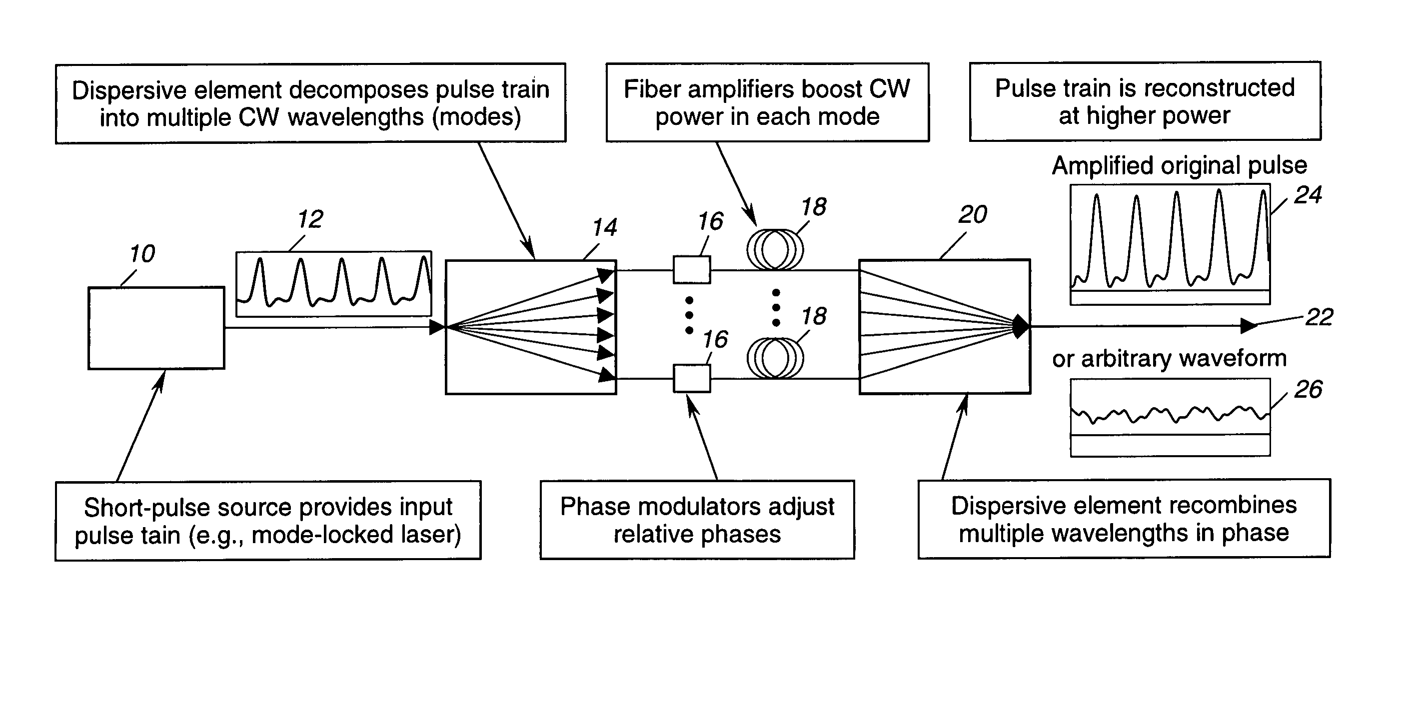
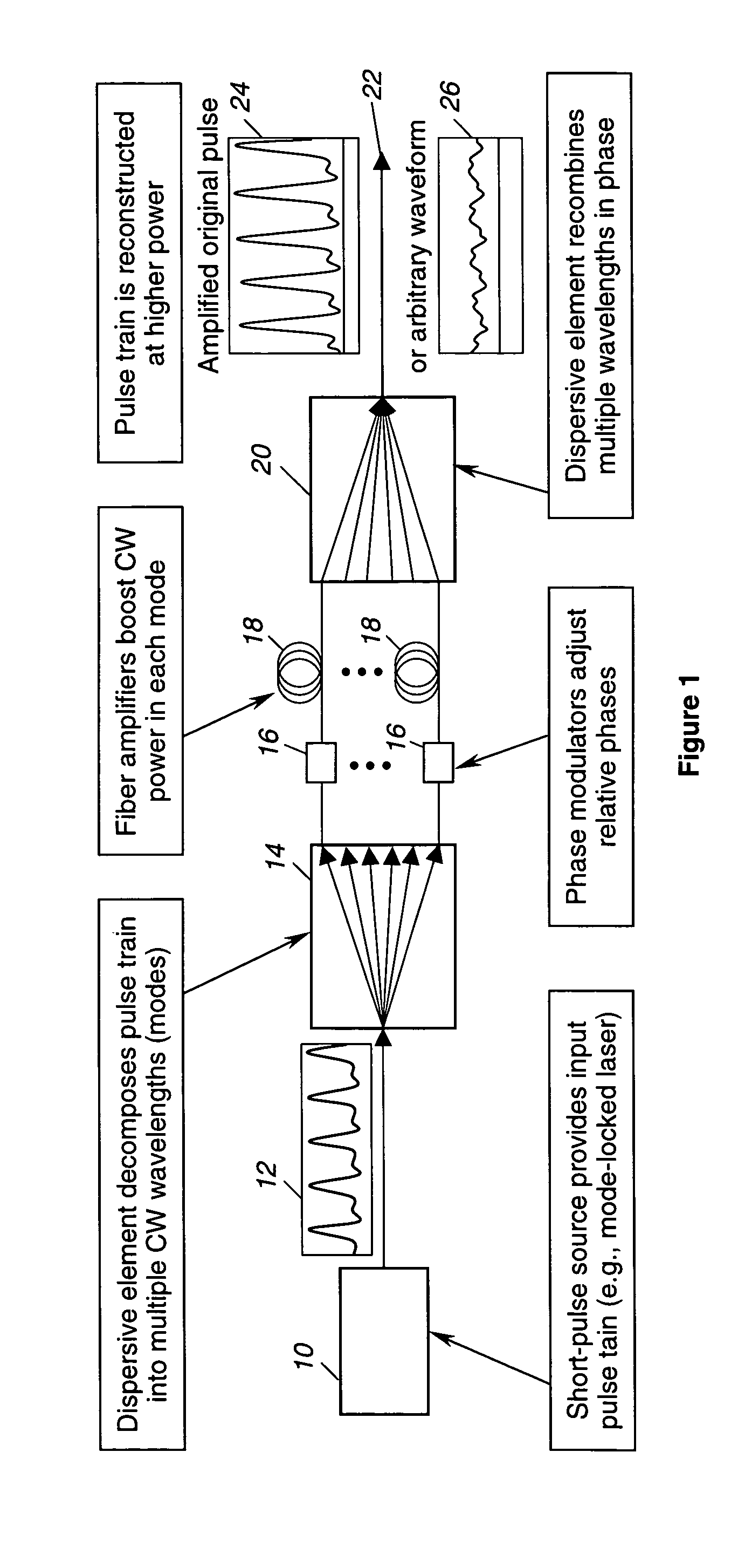
[0012] As shown in the drawings for purposes of illustration, the present invention is concerned with the generation of high-energy optical radiation with a desired waveform, the nature of which is application dependent. For example, optical remote sensing and applications such as infrared / optical countermeasures require modulated waveforms of optical pulse trains. Conventional techniques use amplitude modulation schemes in which a laser beam intensity is varied over time to achieve the desired waveforms. Electro-optic modulation (EOM) and acousto-optic modulation (AOM) are examples of these techniques. EOM provides modulation rates of up to tens of gigahertz (GHz), and AOM operates typically in the range of tens of megahertz (MHz). Choice of materials and device dimensions limits use of these devices to certain wavelength regions and power levels. Also, these high-energy arbitrary waveform sources inherently suffer from low electrical efficiencies.

[0013] In accordance with the inv...


PUM

PropertyMeasurementUnit
energyaaaaaaaaaa
frequencyaaaaaaaaaa
frequency shiftingaaaaaaaaaa

Abstract

A high-energy optical beam generator providing a desired output waveform. The generator includes a master oscillator, such as a mode-locked laser, to generate an input beam, a first dispersive element to decompose the input beam into frequency components, a set of phase and amplitude modulators to modulate the frequency components individually, a set of power amplifiers to amplify the frequency components individually, and a second dispersive element to recombine the amplified and modulated frequency components into a single output beam. Phase control electronics control the modulators to provide the desired waveform for the output beam, based on its intended application and on sensed characteristics of the input beam and the output beam.

Description

BACKGROUND OF THE INVENTION [0001] The present invention relates generally to optical radiation sources and, more particularly, sources of high-energy optical radiation having arbitrary or desired waveforms. In a number of applications, optical radiation with an arbitrary or desired waveform is needed, but typical sources for this purpose effect control of an optical output waveform by pulse suppression and have a relatively low electrical efficiency. Previously available optical sources also lack the ability to provide any desired waveform. The ability to control the waveform of a high-energy optical source has useful applications in laser welding, lidar (light detection and ranging, which is analogous to radar), and infrared countermeasures (IRCM). In the case of IRCM, using a source with low electrical efficiency results in increased weight, which may be unacceptable for airborne IRCM applications. [0002] Accordingly, there has been a need for an optical radiation source of which...

Claims


Application Information

Patent Timeline
Patent Type & Authority Applications(United States)
IPC IPC(8): G02B27/09G02F1/01H01S3/00H01S3/067H01S3/10H01S3/23
CPCG02B27/0905G02B27/0938G02F2203/26G02F2203/54H01S3/2383H01S3/0078H01S3/06754H01S3/10038H01S3/10053H01S3/0057
Inventor WICKHAM, MICHAEL G.KOMINE, HIROSHICHEUNG, ERIC
Owner NORTHROP GRUMMAN SYST CORP
Why Eureka
Try Eureka