High contrast spatial light modulator and method

a spatial light modulator and high contrast technology, applied in the field of micromirror arrays, can solve the problems of low brightness, low contrast ratio of projected images, low brightness of early slm in video applications, etc., and achieve high contrast, good mechanical properties, and enhance optical reflectivity

Active Publication Date: 2005-06-16
SPATIAL PHOTONICS
View PDF9 Cites 92 Cited by
  • Summary
  • Abstract
  • Description
  • Claims
  • Application Information

AI Technical Summary

Benefits of technology

[0011] The present invention is method of manufacturing a high contrast spatial light modulator (SLM) comprising a high active reflection area fill-ratio and non-diffractive micro-mirror array and a high electrostatic efficiency and low surface adhesion control substrate.
[0012] According to another embodiment of the present invention, pairs of torsion hinges are embedded under the cavities to be part of the lower portion of a mirror plate, and are kept a minimum distance under the reflective surface to allow only a gap for a predetermined angular rotation. Each mirror in the array is suspended by a pair of torsion hinges supported by two posts, so each mirror rotates along an axis in the mirror plane. By eliminating the horizontal displacement of individual mirror during the crossover transition, the gaps between adjacent mirrors in the array are significantly reduced, which results in a very high active reflection area fill-ratio of the SLM.
[0013] According to another embodiment of the present invention, a pair of vertical landing tips is fabricated on the surface of a control substrate. These vertical landing tips reduce the contact area of mirrors during the mechanical stops, and improve the reliability of mechanical landing operation. Most importantly, these landing tips enable a mirror landing separation by applying a sharp bipolar pulsing voltage on a common bias of the mirror array. The kinetic energy of the electromechanical shock generated by bipolar pulsing is converted into the elastic strain energy stored in the deformed mirror hinges and deformed landing tips, and is later released to spring and bounce the mirror separating the landing tips.

Problems solved by technology

Early SLM in video applications suffers a disadvantage of low brightness and low contrast ratio of the projected images.
A large inactive area around each pixel in the array of SLM results in a low optical coupling efficiency and low brightness.
The scattered light from these inactive areas in the array forms diffraction patterns that adversely impact the contrast of video images.
However, the vertical mirror support post that elevates the mirror plate above the hinge yoke plate has two negative influences on the contrast ratio of the DMD.
First, a large dimple (caused by the fabrication of mirror support post) is present at the center of the mirror in current designs that causes scattering of the incident light and reduces optical efficiency.
Second, double plate rotation causes a horizontal displacement of mirror surfaces along the surface of DMD, resulting in a horizontal vibration of a micro-mirror during operation.
The yoke structure limits the electrostatic efficiency of the capacitive coupling between the bottom electrodes and the yoke and mirror.
Double plate structures scatter incident light which also reduces the contrast ratio of the video images.
In such a top hanging mirror design, the mirror hanging posts and mechanical stops are all exposed to the light of illumination, which reduces the active reflection area fill-ratio and optical efficiency, and increases the light scattering.
It is also difficult to control the smoothness of reflective mirror surfaces, which is sandwiched between the deposited aluminum film and LPCVD silicon nitride layers.
No post-polishing can be done to correct the mirror roughness.

Method used


Image

  • High contrast spatial light modulator and method
  • High contrast spatial light modulator and method
  • High contrast spatial light modulator and method

Examples


Embodiment Construction

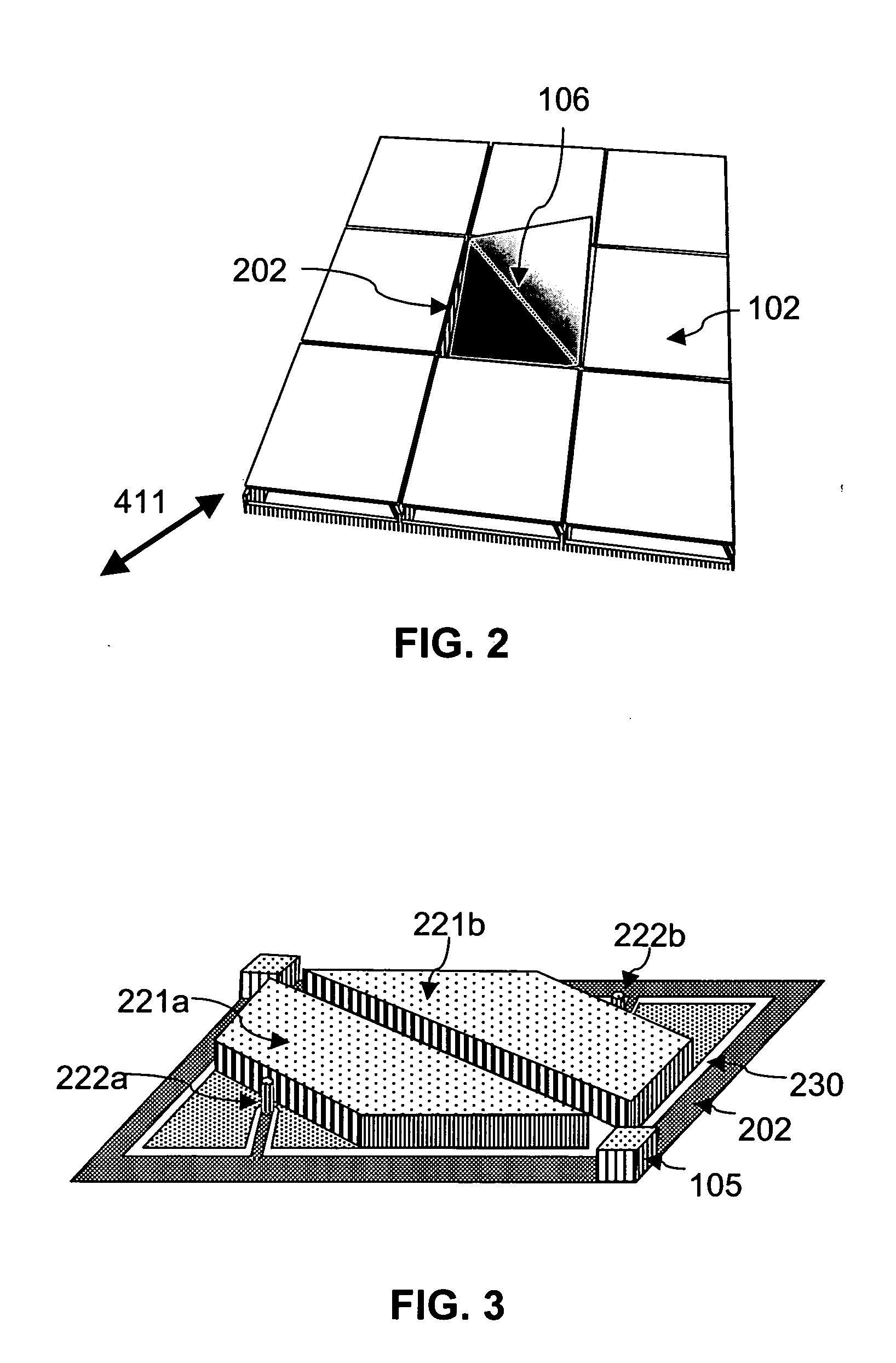
[0035] A high contrast spatial light modulator (SLM) for display and printing is fabricated by coupling a high active reflection area fill-ratio and non-diffractive micro-mirror array with a high electrostatic efficiency and low surface adhesion control substrate.

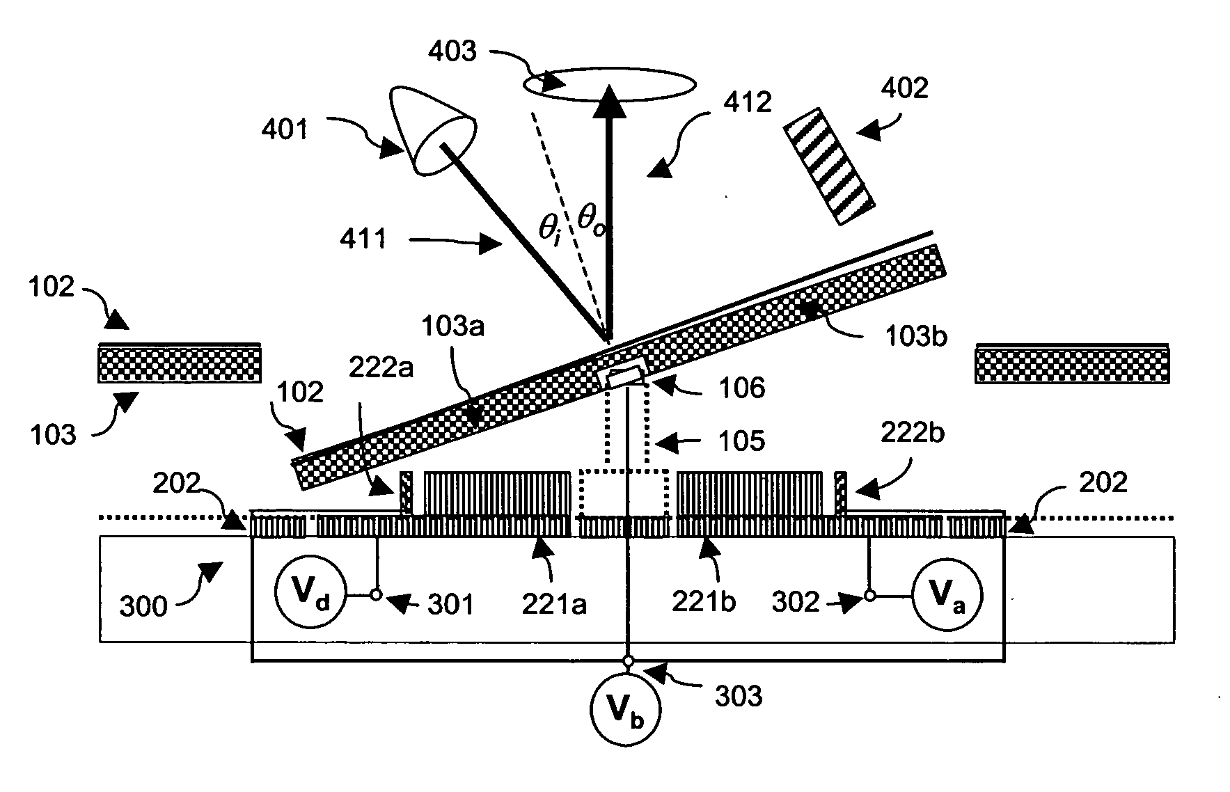
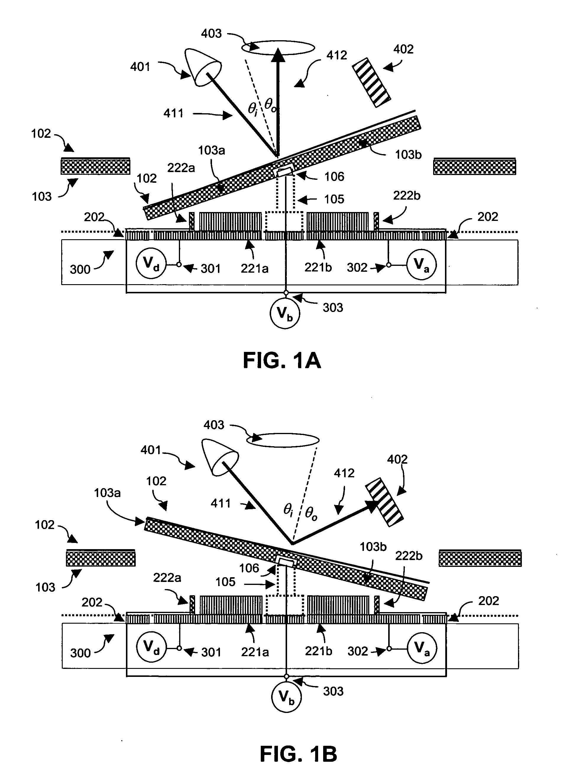
[0036] A cross-sectional view of a part of the spatial light modulator according to one embodiment of the present invention is shown in FIG. 1a, as the directional light 411 from illumination source 401 forms an angle of incidence θi. Deflected light 412 has an angle of θo, as measured in the normal direction of a micro-mirror array. In a digital operation mode, this configuration is commonly called the “on” position.

[0037]FIG. 1b shows a cross section view of the same part of the spatial light modulator while the mirror plate is rotated toward another electrode under the other side of the hinge 106. The directional light 411 and deflected light 412 form much larger angles θi and θo. These angles are a function of the dim...


PUM


Abstract

A high contrast spatial light modulator for display and printing is fabricated by coupling a high active reflection area fill-ratio and non-diffractive micro-mirror array with a high electrostatic efficiency and low surface adhesion control substrate.

Description

CROSS REFERENCE TO RELATED APPLICATIONS [0001] This application claims priority to the U.S. Provisional Patent Application entitled, “High Contrast Spatial Light Modulator and Method”, filed Oct. 27, 2003, Ser. No. 60 / 514,589, the contents of which are incorporated herein by reference.FIELD OF THE INVENTION [0002] This invention relates to arrays of spatial light modulators (SLMs) and their fabrication, and more particularly to a micro-mirror array with electronically addressable control circuitry for display and printing applications. BACKGROUND OF THE INVENTION [0003] Over the past fifteen to twenty years, micro-mirror based spatial light modulators (SLM) have made incremental technical progress and have gained acceptance in the display industry. The devices operate by tilting individual micro-mirror plates in the array around a torsion hinge with an electrostatic torque to deflect the incident light in a predetermined exit direction. In a more popular digital mode operation, the ...

Claims


Application Information

Patent Timeline
Patent Type & Authority Applications(United States)
IPC IPC(8): G02BG02B26/00G02B26/08
CPCG02B26/0841G02B26/0833
Inventor PAN, SHAOHER X.
Owner SPATIAL PHOTONICS
Why Eureka
Try Eureka