Rotary member driving mechanism, and image forming apparatus employing this mechanism

Inactive Publication Date: 2005-06-16
RICOH PRINTING SYST
View PDF5 Cites 12 Cited by
  • Summary
  • Abstract
  • Description
  • Claims
  • Application Information

AI Technical Summary

Benefits of technology

[0010] For a rotary member driving mechanism according to the present invention, a smooth drive waveform is obtained by the continuous

Problems solved by technology

However, the rotation speed fluctuates, depending on changes in the rotation speed of a drive motor that turns the rotary member, vibrations caused by eccentricity of the drive shaft, changes in the speed of a rotation transmission system that occur at the portion where gears engage, or changes in speed caused by inherent vibration due to resonance.
However, considerable mass is required to obtain a satisfactory rotation performance using the flywheel, and not only is the weight of the apparatus increased, but also a support mechanism is required to hold the apparatus.
However, accor

Method used


Image

  • Rotary member driving mechanism, and image forming apparatus employing this mechanism
  • Rotary member driving mechanism, and image forming apparatus employing this mechanism
  • Rotary member driving mechanism, and image forming apparatus employing this mechanism

Examples


first embodiment

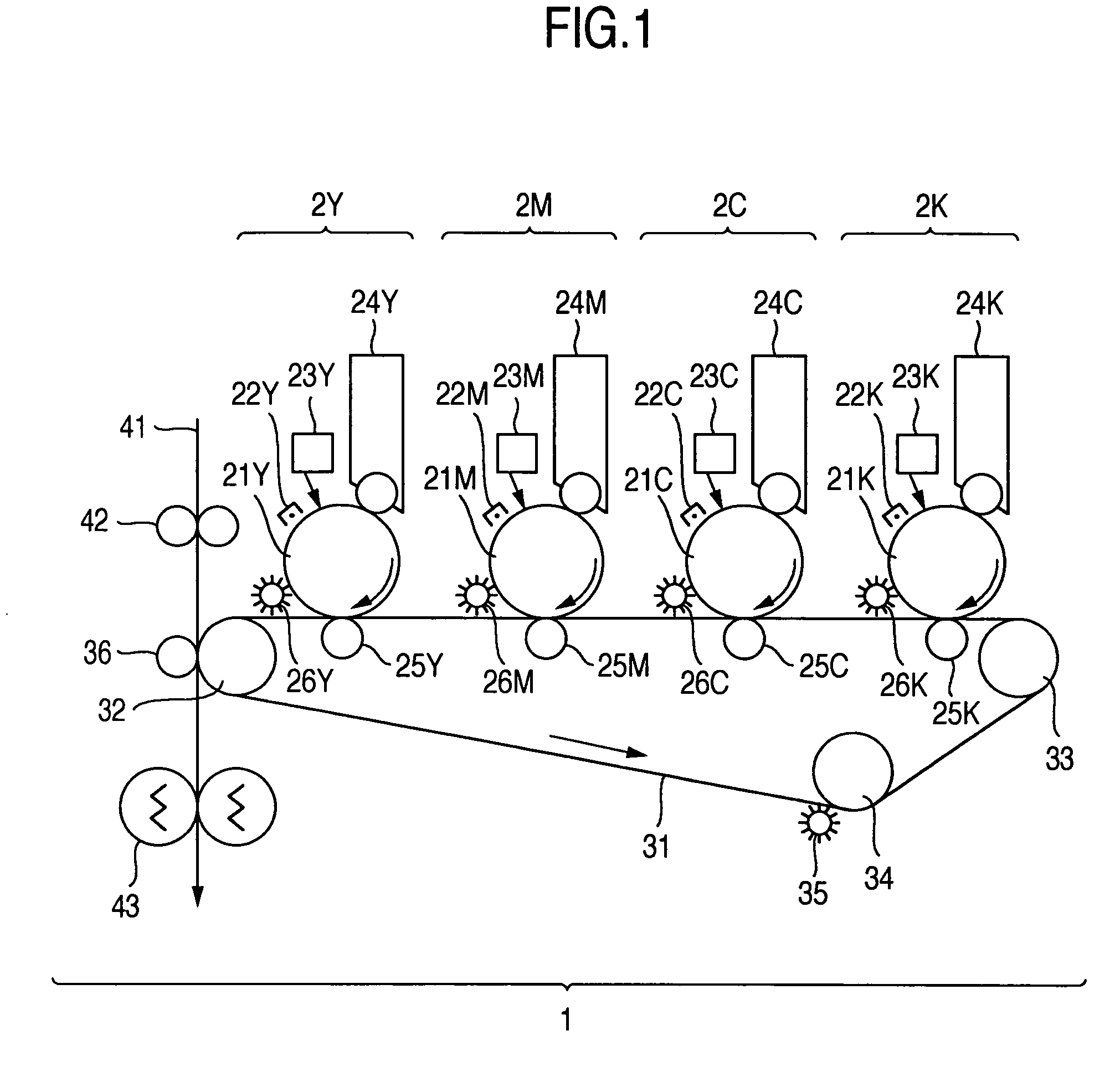
[0019]FIG. 1 is a diagram showing the configuration of an image forming apparatus according to the present invention.

[0020] The image forming apparatus 1 shown in FIG. 1 has a configuration for full-color image developing. To form toner images using four colors, four photosensitive members 21Y, 21M, 21C and 21K, which correspond to the four colors, are provided for the image forming apparatus 1. As printing systems 2, charging devices 22Y, 22M, 22C and 22K, exposure devices 23Y, 23M, 23C and 23K, developing devices 24Y, 24M, 24C and 24K, transfer devices 25Y, 25M, 25C and 25K, and cleaning devices 26Y, 26M, 26C and 26K are provided around the individual photosensitive members 21Y, 21M, 21C and 21K. Further, an intermediate transfer belt 31 is positioned to superimpose toner images formed on the photosensitive members 21Y, 21M, 21C and 21K. Arranged inside the transfer belt 31 are a drive roller 32, idlers 33 and 34 and the transfer devices 25Y, 25M, 25C and 25K, which were previousl...

second embodiment

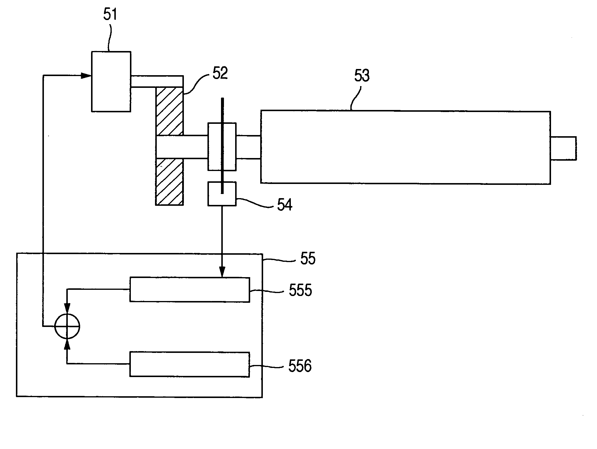
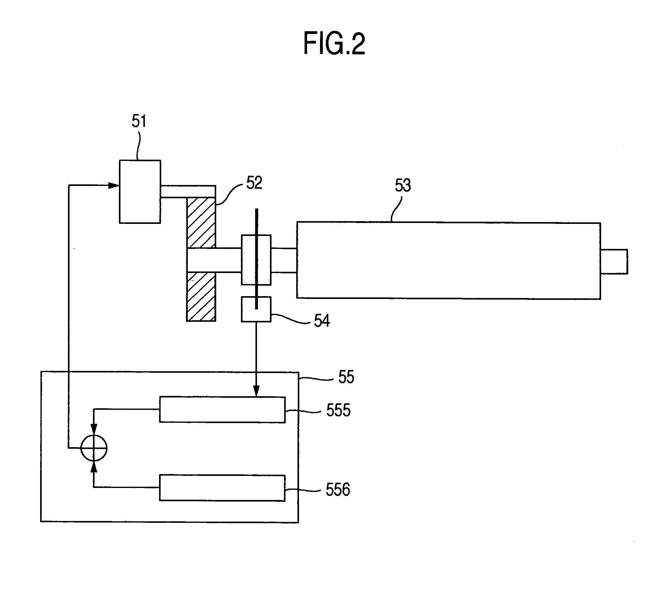
[0027]FIG. 3 is a diagram showing the control blocks for a rotary member driving mechanism according to the invention.

[0028] A controller 55 includes: a pulse interval measurement unit 551, an integration unit 552, an analyzer 553, a function generator 554, the continuous repetition function table 555 and the rotation speed instructed value 556.

[0029] The pulse interval measurement unit 551 measures the interval between pulse signals transmitted by the rotation detector 54. To obtain the interval for the pulse signals, a counter circuit counts the number of reference clocks, which have a considerably higher frequency than the maximum frequency for the pulse signal that is output by the rotation detector 54. Based on a counter value C, a rotation speed Vr (rotations per second) for the rotary member 53 is obtained as Vr=fc / CN, wherein fc denotes the frequency (Hz) of a reference clock, and N denotes the resolution (pulses per rotation) of the rotary encoder. Generally, as is shown i...


PUM


Abstract

For a conventional image forming apparatus, since a waveform in a phase opposite that of a rotation change waveform is applied to a drive motor to rotate a photosensitive member, a correction to cancel the rotation change is also performed for a sudden rotation change of the photosensitive member, or for a high frequency change in the noise component generated by a rotation detector. As a result, since the drive motor can not be smoothly rotated, and since the drive torque of the drive motor is not stabilized, small vibrations always occur in the photosensitive member and cause image deterioration, such as a jitter or banding. Therefore, according to the invention, cycling due to the eccentricity of the photosensitive member is represented by using a continuous repetition function, and the waveform in the opposite phase is employed as a drive instruction value for the driving unit. With this arrangement, smooth rotation of the driving unit can be obtained, and the offsetting of the change is performed.

Description

BACKGROUND OF THE INVENTION [0001] 1. Field of the Invention [0002] The present invention relates to a rotary member driving mechanism that is employed for a color electrophotographic copier, a color printer and an imaging apparatus having an image reader, and that drives rotary members, such as a photosensitive member, a belt drive roller and a document conveying roller, and an image forming apparatus employing this mechanism. [0003] 2. Related Background Art [0004] Rotary members, such as a photosensitive drum, a transfer belt and a paper conveying roller, are employed for an electrophotographic copier or printer. For these rotary members, a constant rotation speed must be maintained in order to provide an accurate image exposure position and an accurate color transfer position. However, the rotation speed fluctuates, depending on changes in the rotation speed of a drive motor that turns the rotary member, vibrations caused by eccentricity of the drive shaft, changes in the speed ...

Claims


Application Information

Patent Timeline
IPC IPC(8): G03G21/14G03G15/00G03G21/00H02P7/00H02P29/00
CPCG03G2215/00075G03G15/5008
Inventor KINOSHITA, YASUSHIMIYASAKA, TORUUOZAKI, YUJI
Owner RICOH PRINTING SYST
Why Eureka
Try Eureka