
Modular frame corners

a modular frame and corner technology, applied in the field of corner pieces for frames, can solve the problem of more expensive frame corners

Inactive Publication Date: 2005-06-16
EXCELL PRODUTS
View PDF11 Cites 43 Cited by
  • Summary
  • Abstract
  • Description
  • Claims
  • Application Information

AI Technical Summary

Benefits of technology

[0011] The connector assembly, which connects the first corner piece to the second corner piece of the modular frame corner is provided with a male connector extending from the intermediate member of the second corner piece and a female connector extending from the intermediate member of the first corner piece. The female connector, which is adapted to matingly receive the male connector, is provided with a length substantially corresponding to the distance between the first and second corner pieces when same are in an assembled position so that the female connector provides a substantially uniform and unbroken surface between the first and second corner pieces.

Problems solved by technology

In this respect, extruded profiles constitute an inexpensive element manufactured by tools while, on the other hand, the frame corners are more expensive because tools with mobile parts are required and also because the detail proper will become more homogenous and requires more material.

Method used


Image

  • Modular frame corners
  • Modular frame corners
  • Modular frame corners

Examples


Embodiment Construction

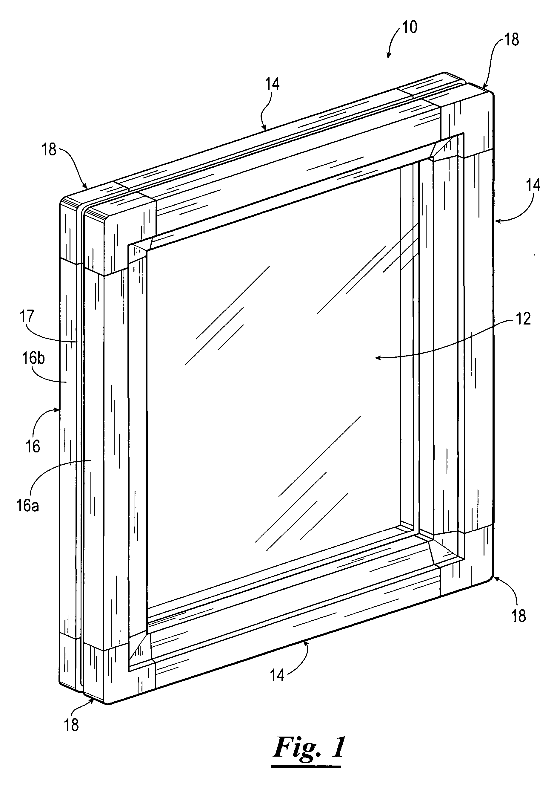
[0012]FIG. 1 is a perspective view of a frame having modular frame corners constructed in accordance with the present invention.

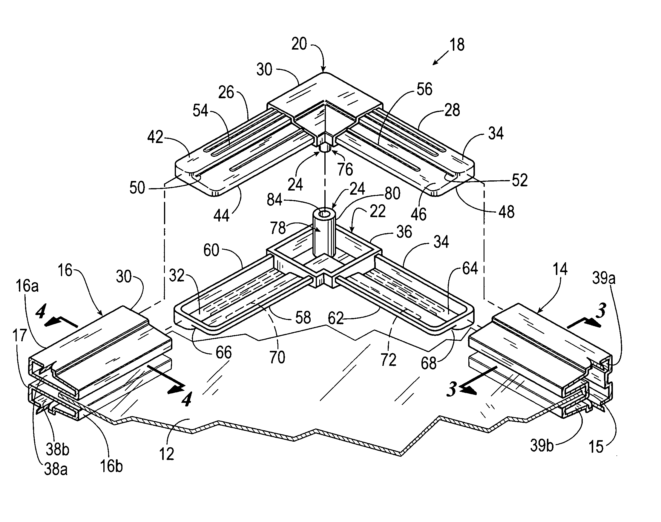
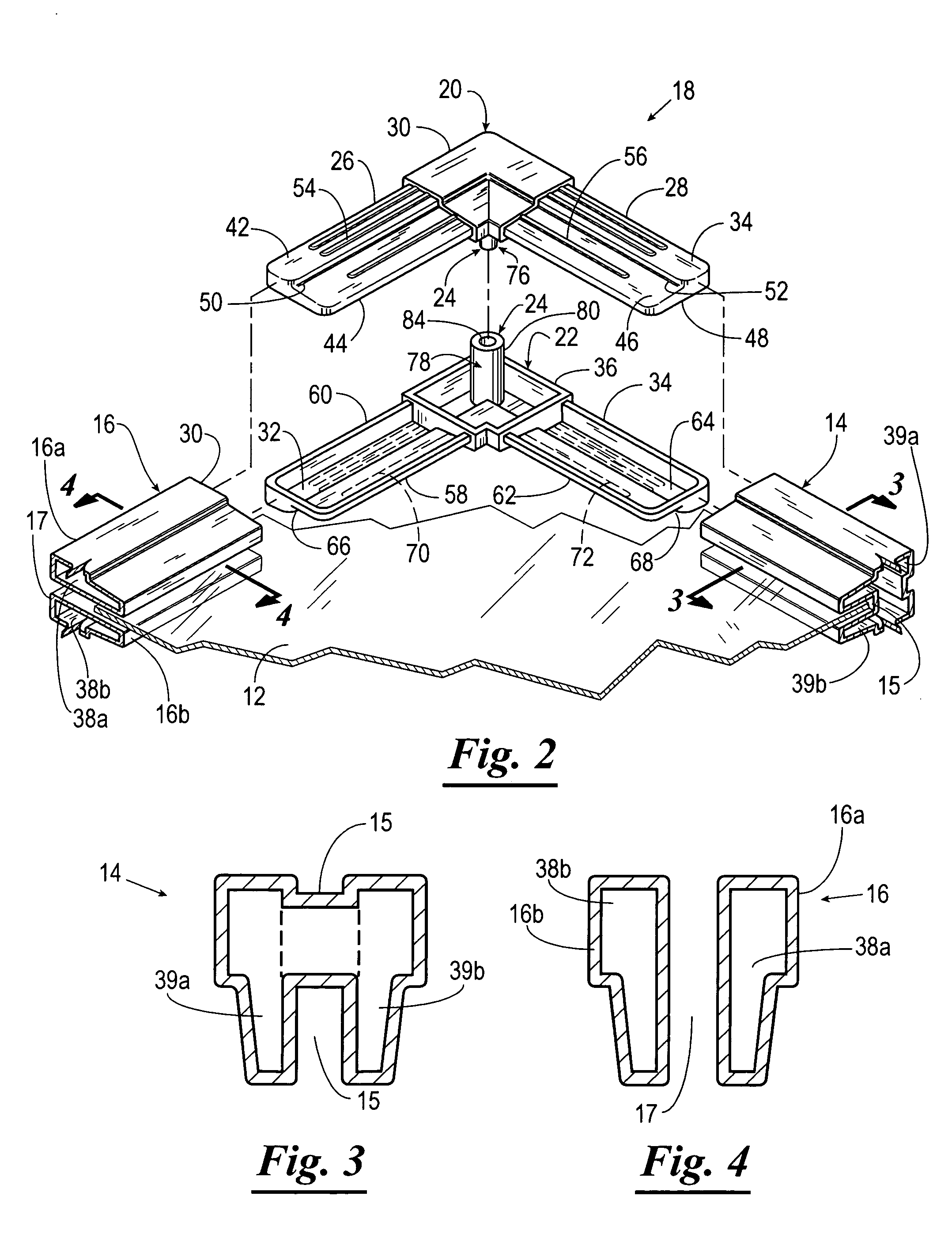
[0013]FIG. 2 is an exploded fragmental perspective view of one of the modular frame corners of FIG. 1.

[0014]FIG. 3 is a cross-sectional view of a frame member of FIG. 2 taken along line 3-3 thereof.

[0015]FIG. 4 is a cross-sectional view of a multi-component frame member of FIG. 2 taken along line 4-4 thereof.

[0016]FIG. 5 is a perspective view of one of the corner pieces of the modular frame corner of the present invention illustrating a second side thereof.

[0017]FIG. 6 is a perspective view illustrating a first side of the second corner piece of the modular frame corner of the present invention.

DETAILED DESCRIPTION

[0018] Referring now to the drawings, and more particularly to FIG. 1, shown therein and designated by the general reference numeral 10 is a frame for securing and displaying a frameable object 12. The frame 10 includes three frame members 1...


PUM


Abstract

A modular frame corner for joining adjacently disposed frame members. The modular frame corner includes a first corner piece, a second corner piece and a connector assembly for connecting the first and second corner pieces. The connector assembly includes a male connector and a female connector adapted to receive the male connector. The female connector is provided with a length substantially corresponding to the distance between the first and second corner pieces when same are in a connected position so that the female connector provides a substantially uniform and unbroken surface between the first and second corner pieces.

Description

CROSS REFERENCE TO RELATED APPLICATIONS [0001] This application claims benefit of U.S. Provisional Application 60 / 528,614, filed Dec. 11, 2003, which is incorporated herein by reference in its entirety.STATEMENT REGARDING FEDERALLY SPONSORED RESEARCH OR DEVELOPMENT [0002] Not applicable. BACKGROUND OF THE INVENTION [0003] 1. Field of the Invention [0004] The present invention generally relates to a corner piece for a frame and, more particularly, to a modular corner piece for frames intended to be used for advertising and display purposes. [0005] 2. Brief Description of Related Art [0006] It is previously known to manufacture frames in long segments or strips and thereafter cut them to the desired length in order to constitute the sides of the frames. The profiles are interconnected via corner pieces so as to form a complete frame. [0007] Frames for advertising and information purposes often are used only once, e.g. at fairs, exhibitions and the like. Therefore, it is desirable that...

Claims


Application Information

Patent Timeline
IPC IPC(8): E06B3/54E06B3/964F16D1/00G09F1/12G09F15/00
CPCE06B3/5454E06B3/9641Y10T403/73G09F1/12G09F15/0012E06B2003/5472F16B2200/67
Inventor MEDCALF, MERLE D.MEDCALF, MICHAEL D.
Owner EXCELL PRODUTS
Features
  • Generate Ideas
  • Intellectual Property
  • Life Sciences
  • Materials
  • Tech Scout
  • Unparalleled Data Quality
  • Higher Quality Content
  • 60% Fewer Hallucinations
Learn More